
Manual

Layer 2 Tunnel Protocol Version 3
Configuration Examples for Layer 2 Tunnel Protocol Version 3
67
Cisco IOS Releases 12.0(29)S and 12.2(25)S
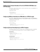
Verifying an L2TP Control Channel Example
To display detailed information the L2TP control channels that are set up to other L2TP-enabled devices
for all L2TP sessions on the router, use the show l2tun tunnel all command. The L2TP control channel
is used to negotiate capabilities, monitor the health of the peer PE router, and set up various components
of an L2TPv3 session.
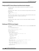
Router# show l2tun session all
Session Information Total tunnels 0 sessions 1
Session id 111 is up, tunnel id 0
Call serial number is 0
Remote tunnel name is
Internet address is 10.0.0.1
Session is manually signalled
Session state is established, time since change 00:06:05
0 Packets sent, 0 received
0 Bytes sent, 0 received
Receive packets dropped:
out-of-order: 0
total: 0
Send packets dropped:
exceeded session MTU: 0
total: 0
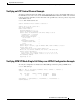
Session vcid is 123
Session Layer 2 circuit, type is ATM VPC CELL, name is ATM3/0/0:1000007
Circuit state is UP
Remote session id is 222, remote tunnel id 0
DF bit off, ToS reflect disabled, ToS value 0, TTL value 255
Session cookie information:
local cookie, size 8 bytes, value 00 00 00 00 00 00 00 64
remote cookie, size 8 bytes, value 00 00 00 00 00 00 00 C8
SSS switching enabled
Sequencing is off
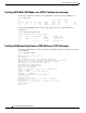
Verifying ATM VP Mode Single Cell Relay over L2TPv3 Configuration Example
To verify the configuration of a PVP, use the show atm vp command in privileged EXEC mode:
Router# show atm vp 5
ATM4/1/0 VPI: 5, Cell-Relay, PeakRate: 155000, CesRate: 0, DataVCs: 0,
CesVCs: 0, Status: ACTIVE
VCD VCI Type InPkts OutPkts AAL/Encap Status
8 3 PVC 0 0 F4 OAM ACTIVE
9 4 PVC 0 0 F4 OAM ACTIVE
TotalInPkts: 0, TotalOutPkts: 0, TotalInFast: 0, TotalOutFast: 0,
TotalBroadcasts: 0