
Manual

Layer 2 Tunnel Protocol Version 3
Configuration Examples for Layer 2 Tunnel Protocol Version 3
59
Cisco IOS Releases 12.0(29)S and 12.2(25)S
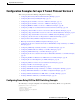
Configuring QoS for L2TPv3 on the Cisco 12000 Series Example
To apply a QoS policy for L2TPv3 to a Frame Relay interface on a Cisco 12000 series 2-port Ch
OC-3/STM-1 (DS1/E1) or 6-port Ch T3 line card, you must:
• Use the map-class frame-relay class-name command in global configuration mode to apply a QoS
policy to a Frame Relay class of traffic.
• Use the frame-relay interface-dcli dcli-number switched command (in interface configuration
mode) to enter Frame Relay DLCI interface configuration mode and then the class command to
configure a QoS policy for a Frame Relay class of traffic on the specified DLCI. You must enter a
separate series of these configuration commands to configure QoS for each Frame Relay DLCI on
the interface.
As shown in the following example, when you configure QoS for L2TPv3 on the ingress side of a
Cisco 12000 series Frame Relay interface, you must also configure the value of the ToS byte used in IP
headers of tunneled packets when you configure the L2TPv3 pseudowire (see the section “Configuring
the L2TPv3 Pseudowire”).
The following example shows the MQC commands and ToS byte configuration used on a Cisco 12000
series router to apply a QoS policy for DLCI 100 on the ingress side of a Frame Relay interface
configured for L2TPv3 tunneling:
policy-map frtp-policy
class class-default
police cir 8000 bc 6000 pir 32000 be 4000 conform-action transmit exceed-action
set-frde-transmit violate-action drop
map-class frame-relay fr-map
service-policy input frtp-policy
interface Serial0/1/1:0
encapsulation frame-relay
frame-relay interface-dlci 100 switched
class fr-map
connect frol2tp1 Serial0/1/1:0 100 l2transport
xconnect 10.0.3.201 666 encapsulation l2tpv3 pw-class aaa
pseudowire-class aaa
encapsulation l2tpv3
ip tos value 96
To apply a QoS policy for L2TPv3 to the egress side of a Frame Relay interface on a Cisco 12000 series
2-port Ch OC-3/STM-1 (DS1/E1) or 6-port Ch T3 line card, you must:
• Use the match ip precedence command in class-map configuration mode to configure the IP
precedence value used to determine the egress queue for each L2TPv3 packet with a Frame Relay
payload.
• Use the random-detect command in policy-map class configuration mode to enable a weighted
random early detection (WRED) drop policy for a Frame Relay traffic class that has a bandwidth
guarantee. Use the random-detect precedence command to configure the WRED and modified
deficit round robin (MDRR) parameters for particular IP Precedence values.
The next example shows the MQC commands used on a Cisco 12000 series Internet Router to apply a
QoS policy with WRED/MDRR settings for specified IP Precedence values to DLCI 100 on the egress
side of a Frame Relay interface configured for L2TPv3:
class-map match-all d2
match ip precedence 2
class-map match-all d3
match ip precedence 3