
Manual

Layer 2 Tunnel Protocol Version 3
Information About Layer 2 Tunnel Protocol Version 3
21
Cisco IOS Releases 12.0(29)S and 12.2(25)S
CIR Guarantees
In order to provide committed information rate (CIR) guarantees, you can configure a queueing policy
that provides bandwidth to each DLCI to the interface facing the customer network on the egress PE.
Note CIR guarantees are supported only on the Cisco 7500 series with dCEF. This support requires that the
core has sufficient bandwidth to handle all CE traffic and that the congestion occurs only at the egress
PE.
Binding L2TPv3 Sessions to Multilink Frame Relay Interfaces
The configuration of an L2TPv3 session on a Multilink Frame Relay (MLFR) bundle interface is
supported only on Cisco 12000 series Two-Port Channelized OC-3/STM-1 (DS1/E1) and Six-Port
Channelized T3 (T1) line cards.
The Multilink Frame Relay feature introduces functionality based on the Frame Relay Forum Multilink
Frame Relay UNI/NNI Implementation Agreement (FRF.16). This feature provides a cost-effective way
to increase bandwidth for particular applications by enabling multiple serial links to be aggregated into
a single bundle of bandwidth.
For an example of how to configure L2TPv3 tunneling on a multilink Frame Relay bundle interface, see
Configuring MLFR for L2TPv3 on the Cisco 12000 Series Example, page 60.
For information about how configure and use the MLFR feature, refer to the Multilink Frame Relay
(FRF.16) publication.
Ethernet
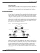
An Ethernet frame arriving at a PE router is simply encapsulated in its entirety with an L2TP data header.
At the other end, a received L2TP data packet is stripped of its L2TP data header. The payload, an
Ethernet frame, is then forwarded to the appropriate attachment circuit.
Because the L2TPv3 tunneling protocol serves essentially as a bridge, it need not examine any part of
an Ethernet frame. Any Ethernet frame received on an interface is tunneled, and any L2TP-tunneled
Ethernet frame is forwarded out the interface.
Note Due to the way in which L2TPv3 handles Ethernet frames, an Ethernet interface must be configured to
promiscuous mode in order to capture all traffic received on the Ethernet segment attached to the router.
All frames will be tunneled through the L2TP pseudowire.
802.1q (VLAN)
L2TPv3 supports VLAN membership in the following ways:
• Port-based, in which undated Ethernet frames are received
• VLAN-based, in which tagged Ethernet frames are received
In L2TPv3, Ethernet Xconnect supports port-based VLAN membership and the reception of tagged
Ethernet frames. A tagged Ethernet frame contains a tag header (defined in 802.1Q), which is 4 bytes
long and consists of a 2-byte tag protocol identifier (TPID) field and a 2-byte tag control information
(TCI) field. The TPID indicates that a TCI follows. The TCI is further broken down into the following
three fields: