
Manual

Layer 2 Tunnel Protocol Version 3
Information About Layer 2 Tunnel Protocol Version 3
20
Cisco IOS Releases 12.0(29)S and 12.2(25)S
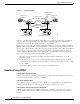
For example, in Figure 1, CE R3 and PE R1 are Frame Relay LMI peers; CE R4 and PE R2 are also LMI
peers. You can use a different type of LMI between CE R3 and PE R1 compared to what you use between
CE R4 and PE R2.
The CE devices may be a Frame Relay switch or end-user device. Each Frame Relay PVC is composed
of multiple segments. The DLCI value is local to each segment and is changed as traffic is switched from
segment to segment. Note that, in Figure 1, two Frame Relay PVC segments are connected by a
pseudowire. Frame Relay header flags (FECN, BECN, C/R, DE) are preserved across the pseudowire.
PVC Status Signaling
PVC status signaling is propagated toward Frame Relay end users by the LMI protocol. You can
configure the LMI to operate in any of the following modes:
• UNI DTE mode—PVC status is not reported, only received.
• UNI DCE mode—PVC status is reported but not received.
• NNI mode—PVC status is reported and received independently.
L2TPv3 supports all three modes.
The PVC status should be reported as ACTIVE only if the PVC is available from the reporting device to
the Frame Relay end-user device. All interfaces, line protocols, and pseudowires must be operational
between the reporting device and the Frame Relay end-user device.
Note that any keepalive functions on the session are independent of Frame Relay, but any state changes
that are detected are fed into the PVC status reporting. For example, the L2TP control channel uses hello
packets as a keepalive function. If the L2TPv3 keepalive fails, all L2TPv3 sessions are torn down. Loss
of the session is notified to Frame Relay, which can then report PVCs INACTIVE to the CE devices.
For example, in Figure 1, CE R3 reports ACTIVE to PE R1 only if the PVC is available within CE R3.
When CE R3 is a switch, it reports all the way to the user device in the customer network.
PE R1 reports ACTIVE to CE R3 only if the PVC is available within PE R1 and all the way to the
end-user device (via PE R2 and CE R3) in the other customer VPN site.
The ACTIVE state is propagated hop-by-hop, independently in each direction, from one end of the
Frame Relay network to the other end.
Sequencing
Frame Relay provides an ordered service in which packets sent to the Frame Relay network by one
end-user device are delivered in order to the other end-user device. When switching is occurring over the
pseudowire, packet ordering must be able to be preserved with a very high probability to closely emulate
a traditional Frame Relay service. If the CE router is not using a protocol that can detect misordering
itself, configuring sequence number processing may be important. For example, if the Layer 3 protocol
is IP and Frame Relay is therefore used only for encapsulation, sequencing is not required. To detect
misordering, you can configure sequence number processing separately for transmission or reception.
For more information about how to configure sequencing, see the section “Configuring a Negotiated
L2TPv3 Session for Local HDLC Switching Example.”
ToS Marking
The ToS bytes in the IP header can be statically configured or reflected from the internal IP header. The
Frame Relay discard eligible (DE) bit does not influence the ToS bytes.