
User Guide
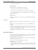
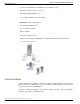
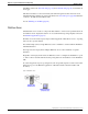
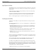
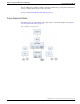

Table Of Contents
- Cover Page
- Table of Contents
- List of Figures
- Figure 1 : Central Controller
- Figure 2 : Peripheral and Peripheral Gateway
- Figure 3 : Administrative Workstation
- Figure 4 : WebView Server
- Figure 5 : Diagram of System Components
- Figure 6 : ICM Data Environment
- Figure 7 : Real-Time Data Moves to AW Local Database
- Figure 8 : Icons for Graphs and Tables
- Figure 9 : Deployment with Enterprise Routing
- Figure 10 : Sample Script for Enterprise Routing
- Figure 11 : Script Example for Agent Level Routing
- Figure 12 : Sample Script for Hybrid Routing
- Figure 13 : Agent State and Task State Relationship
- Figure 14 : Sample Routing Script for Information Gathering and Queuing
- Figure 15 : Call Type Data for Calls that Abandon after Call Type is Changed
- Figure 16 : Call Type Data for Calls that Abandon before Call Type is Changed
- Figure 17 : MultiChannel Options
- Figure 18 : Agent State Hierarchy
- Figure 19 : Call Abandoned While On Hold Scenario
- Preface
- Chapter 1: System Architecture and Reporting
- Chapter 2: Understanding Reporting
- Chapter 3: Understanding Routing and Queuing
- Chapter 4: Planning for Reporting
- Planning for Reporting at Unified ICM Setup
- Planning for Your Deployment
- Planning for Configuration and Scripting
- Planning for Agent Reporting
- Planning for Call Types
- Planning for Custom Reporting
- Planning for the HDS
- Planning for Enterprise Routing and Enterprise Reporting
- Planning for Service and Enterprise Service Reporting
- Planning for Service Level
- Planning for Short Calls
- Planning for Skill Groups and Enterprise Skill Groups
- Planning for Transfer and Conference Reporting
- Planning for Translation Routing
- Planning for Unexpected Scripting Conditions
- Planning for VRU Application Reporting
- Chapter 5: Reporting on Agents
- What Agent Data do you Want to See?
- Reporting on Agent Activity in Skill Groups
- Reporting on Agent States
- Reporting on Average Speed of Answer for Agents and Skill Groups
- Reporting on Agent Logout Reason Codes
- Reporting on Agent Not Ready Reason Codes
- Reporting on Agent Task Handling
- Reporting on Agent Performance for Outbound Option Dialing Campaign Calls
- Reporting on Agent Redirection on No Answer
- Reporting on Agent Call Transfers and Conferences
- Reporting on Agent Teams
- Chapter 6: Reporting on Customer Experience
- Chapter 7: Reporting on Operations
- Chapter 8: Reporting in a MultiChannel Environment
- Chapter 9: Sample Call Scenario
- Chapter 10: Reporting Implications of Data Loss and Component Failover
- Chapter 11: Troubleshooting Report Data
- Appendix A: List of All Unified ICM Report Templates
- Appendix B: Reporting Entities and Databases
- Appendix C: Configuration and Scripting for Reporting
- Configuration for Agent Reporting
- Configuring Call Types
- Configuration and Scripting for Conferences and Transfers
- Configuring Services and Enterprise Services
- Configuring and Scripting for Service Level Threshold and Type
- Configuring Short Calls
- Configuring Skill Groups and Enterprise Skill Groups
- Configuration and Scripting for the VRU
- Configuring Translation Routes
- Index

Process on the CallRouter, which is called the Central Controller Agent (CC Agent). The protocol
used between the two agent processes is the Device Management Protocol (DMP).
Open Peripheral Interface Data Elements
To interface with the Central Controller Agent, OPC uses the Open Peripheral Interface (OPI).
The Open Peripheral Interface (OPI) defines the objects that control the flow of OPCI messages
from OPC to the Router. Each table in the Central Database has a set of fields that the Router
uses to make its routing decisions. OPI defines tags for each of those fields.
As elements change, based on events and updates from the ACD, OPC informs the Router of
the changed values based on table type, tag, and value. OPC only sends to the Router those data
elements that have changed in value. Types of OPI data elements reported to the CallRouter
are: Now, Half, To5, Today. See Chapter 2 (page 23) for a discussion of these data elements.
Computer Supported Telephony Application Message Example
To illustrate how Computer Supported Telephony Application (CSTA) messages from the PIM
are translated into OPI data elements, it might help to examine one CSTA message:
CSTAEstablished.
Several OPC state transitions occur when OPC receives this message. The CSTAEstablished
event indicates that a call has been answered by a device (that is, an agent, trunk, or voice port).
When OPC receives this event, the following OPC state transitions take place:
•
If the call was Queued, several database elements and call objects are changed:
–
The count for CallsQNow is reduced by one (-1).
CallsQNow is a database element for services and routes that tracks the number of calls
currently in queue at the peripheral.
–
The call object used to track the CallsQNow and CallQNowTime data elements is removed
from the Call Queued object for the service and/or route associated with the call.
CallsQNowTime is a database element that records the time in seconds that all calls
currently in queue to the service or route have spent in the queue.
–
The CallsLeftQTo5 data element for the service and/or route associated with the call is
increased by one (+1).
CallsLeftQ is a database element that provides the total number of calls to the service or
route that were removed from queue during the current five-minute interval. CallsLeftQ
is also used to calculate expected delay.
–
LocalQTime is written in the Termination_Call_Detail table.
LocalQTime is the time in seconds that the call was in the local queue at the peripheral.
The Termination_Call_Detail record contains information about how each call was handled
Reporting Guide for Cisco Unified ICM Enterprise & Hosted Release 7.2(1)
12
Chapter 1: System Architecture and Reporting
Peripherals and Peripheral Gateways