OL-31086-01 Cisco D9854/D9854-I Advanced Program Receiver Software Version 4.
Please Read This Entire Guide Veuillez lire entièrement ce guide Bitte das gesamte Handbuch durchlesen Sírvase leer completamente la presente guía Si prega di leggere completamente questa guida Important Please read this entire guide before you install or operate this product. Give particular attention to all safety statements. Important Veuillez lire entièrement ce guide avant d'installer ou d'utiliser ce produit. Prêtez une attention particulière à toutes les règles de sécurité.
Notices Trademark Acknowledgments Cisco and the Cisco logo are trademarks or registered trademarks of Cisco and/or its affiliates in the U.S. and other countries. To view a list of Cisco trademarks, go to this URL: www.cisco.com/go/trademarks. Manufactured under license from Dolby Laboratories. Dolby and the double-D symbol are trademarks of Dolby Laboratories. The DVB logo is a registered trademark of the DVB Project. Other third party trademarks mentioned are the property of their respective owners.
AVC/MPEG-4/H.264 Products With respect to each AVC/MPEG-4/H.264 product, Cisco is obligated to provide the following notice: THIS PRODUCT IS LICENSED UNDER THE AVC PATENT PORTFOLIO LICENSE FOR THE PERSONAL AND NON-COMMERCIAL USE OF A CONSUMER TO (i) ENCODE VIDEO IN COMPLIANCE WITH THE AVC STANDARD ("AVC VIDEO") AND/OR (ii) DECODE AVC VIDEO THAT WAS ENCODED BY A CONSUMER ENGAGED IN A PERSONAL AND NON-COMMERCIAL ACTIVITY AND/OR WAS OBTAINED FROM A VIDEO PROVIDER LICENSED TO PROVIDE AVC VIDEO.
Safety Precautions Safety Precautions 1 Read Instructions – All the safety and operating instructions should be read before the product is operated. 2 Retain Instructions – The safety and operating instructions should be retained for future reference. 3 Heed Warnings – All warnings on the product and in the operating instructions should be adhered to. 4 Follow Instructions – All operating and use instructions should be followed.
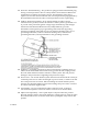
Safety Precautions Use only with a cart, stand, tripod, bracket, or table recommended by the manufacturer, or sold with the product. Any mounting of the product should follow the manufacturer’s instructions, and should use a mounting accessory recommended by the manufacturer. 8 A product and cart combination should be moved with care. Quick stops, excessive force, and uneven surfaces may cause the product and cart combination to overturn.
Safety Precautions 13 Protective Attachment Plug – The product is equipped with an attachment plug having overload protection. This is a safety feature. See Instruction Manual for replacement or resetting of protective device. If replacement of the plug is required, be sure the service technician has used a replacement plug specified by the manufacturer that has the same overload protection as the original plug.
Safety Precautions 19 Servicing – Do not attempt to service this product yourself as opening or removing covers may expose you to dangerous voltage or other hazards. Refer all servicing to qualified service personnel.
Safety Precautions You may find this symbol on the product and/or in the literature that accompanies this product. It indicates a live terminal; the symbol pointing to the terminal device. You may find this symbol on the product and/or in the literature that accompanies this product. It indicates a protective earth terminal. You may find this symbol on the product and/or in the literature that accompanies this product. It indicates excessive or dangerous heat. Power Important! This is a Class I product.
Safety Precautions Règles de sécurité Protégez-vous des risques d'électrocution et protégez votre système contre les endommagements éventuels. Ce produit respecte les standards internationaux de sécurité et de conception. Veuillez observer toutes les procédures de sécurité qui apparaissent dans ce guide, ainsi que les symboles de sécurité qui figurent sur le produit. Si, du fait des circonstances, ce produit cesse de fonctionner normalement, cessez de l'utiliser et empêchez-en l'utilisation future.
Safety Precautions Ne marchez pas sur les câbles ou les prises et n'y exercez aucune pression. Réparations effectuées à l'usine Ne confiez les travaux de réparations qu'au personnel autorisé par l'usine. Sicherheitsvorkehrungen Schützen Sie sich gegen elektrischen Schlag, und Ihr Gerät gegen Beschädigung! Dieses Gerät entspricht internationalen Sicherheits-und Ausführungsnormen. Beachten Sie alle in diesem Handbuch enthaltenen Sicherheitshinweise sowie die am Gerät angebrachten Warnzeichen.
Safety Precautions Kabel Vor jeglicher Wartung des Gerätes sind alle Kabel zu entfernen. Hierzu grundsätzlich am Stecker oder Verbindungsstück und niemals am Kabel selber ziehen. Nicht auf die Kabel oder Stecker treten oder diese einer Zugbelastung aussetzen. Hersteller-Wartung Wartungsarbeiten sind nur durch vom Hersteller autorisierte Techniker vorzunehmen.
Safety Precautions Cubierta No permita que la humedad penetre en este producto. No abra la cubierta del producto a menos que se indique lo contrario. No introduzca objetos a través de las aberturas de la cubierta del producto. Cables Siempre desconectar todos los cables eléctricos antes de revisar o reparar el producto. Tire siempre del enchufe o del conector para desconectar un cable. Nunca tire del cable mismo. No camine ni aplique presión sobre los cables o enchufes..
Safety Precautions Collegare questo prodotto solamente alla fonte di alimentazione indicata sul pannello posteriore di questo prodotto. Se questo prodotto non è dotato di un interruttore principale, il cavo di alimentazione funge a questo scopo. Chiusura Proteggete da umidità questo prodotto. Non aprire la chiusura di questo prodotto a meno che non sia specificato diversamente. Non inserire oggetti attraverso le fessure della chiusura.
Contents Safety Precautions About This Guide v xxiii Objective ................................................................................................................. xxiii Audience ................................................................................................................ xxiii Required Knowledge............................................................................................ xxiii Chapter 1 Introduction 1 D9854/D9854-I Advanced Program Receiver ..............
Installing the D9854/D9854-I Receiver ............................................................................... 26 Rack Mounted ........................................................................................................... 26 Cooling ....................................................................................................................... 26 Grounding..................................................................................................................
Main Menu.............................................................................................................................. 51 Status Menu ............................................................................................................................ 52 Status Menu: General ............................................................................................... 53 Status Menu: Services ...........................................................................................
Viewing the Current Input Status ........................................................................ 164 Setting up the ASI Input ........................................................................................ 166 Configuring the IP Input........................................................................................ 167 Setting up SI Receive Parameters ......................................................................... 175 Setting up Muting Threshold Controls ...................
Viewing Alarm/Warning History........................................................................ 277 Viewing Version Information ............................................................................... 278 Setting up Import/Export File Information ........................................................ 282 Setting up Import/Export FTP Information ....................................................... 284 Managing D9854/D9854-I Web GUI Accounts ..................................................
Alarm Interface ....................................................................................................... 376 Contact Closure Interface ...................................................................................... 377 Power and General Specifications ..................................................................................... 378 General ..................................................................................................................... 378 Power ............
Declaration of Conformity ..................................................................................................
About This Guide About This Guide Objective This guide describes how to install, use and maintain the Cisco D9854/D9854-I Advanced Program Receiver. Note: The guide describes all available options for the D9854/D9854-I receiver. Your D9854/D9854-I receiver may only have some of the features described in this guide.
1 Chapter 1 Introduction Overview This chapter is a general introduction to the Cisco D9854/D9854-I Advanced Program Receiver. It describes the most common applications and interfaces of the receiver. In This Chapter OL-31086-01 D9854/D9854-I Advanced Program Receiver .................................... 2 Transport Stream Inputs/Outputs ....................................................... 5 Disaster Recovery ...................................................................................
Chapter 1 Introduction D9854/D9854-I Advanced Program Receiver The D9854/D9854-I Advanced Program Receiver is designed for satellite content distribution applications requiring DVB-S and DVB-S2 reception capabilities with advanced digital outputs for digital tier program distribution. A built-in decoder will be capable of decoding a MPEG-2 or MPEG-4 High Definition (HD) program for analog monitoring or high-quality HD-SDI output version will be available for reencode applications.
D9854/D9854-I Advanced Program Receiver MPEG and Dolby Digital audio decoding DVB or Imitext subtitling Four audio outputs providing either two stereo pairs or four mono channels of balanced, audio, each with the ability to use part of their output for applications such as SAP, cue tones, etc. Utility data up to 38.
Chapter 1 Introduction AES-3id digital audio output Multi Program Transport Stream (MPTS) MPEG over IP (MPEGoIP) output MPEGoIP Input (D9854-I only) FEC capability for MPEGoIP input and output (D9854-I only) Disaster Recovery capability SFN Model Receivers The Single Frequency Network (SFN) receivers do not include some of the key features normally equipped on D9854 receivers, such as Digital Program Mapping (DPM), MPEGoIP output, and transport stream null packet stuffing.
Transport Stream Inputs/Outputs Transport Stream Inputs/Outputs DVB-ASI Output The D9854/D9854-I receiver has one DVB-ASI output. This output can be used as an input for a DVB-T transmitter or other types of DVB-ASI reception equipment. MPEGoIP Output The MPEGoIP output provides a number of output modes including the capability of carrying a decrypted program for digital tier distribution.
Chapter 1 Introduction The diagram below shows an example of the D9854/D9854-I receiver used in an MPE application. HD-SDI Outputs The D9854/D9854-I Advanced Program Receiver is designed for satellite content distribution applications requiring DVB-S and DVB-S2 reception capabilities with advanced digital outputs for digital tier program distribution. A built-in decoder is capable of decoding an MPEG-2 or MPEG-4 High Definition (HD) program for analog monitoring.
Transport Stream Inputs/Outputs The diagram below shows an example of the D9854-I receiver receiving MPEGoIP transport streams: OL-31086-01 7
Chapter 1 Introduction Disaster Recovery In the event of a transmission failure on the primary feed, the disaster recovery allows for continued programming, with limited to no downtime.
Disaster Recovery If the acquisition fails or there is no signal lock on the backup 1 transport, the receiver will continue to search for the next backup transport for PE1 (Backup 2 transport). If the acquisition is successful on the backup 2 transport, the receiver will set PE1 to channel 101, but leave PE2 to channel 2 because PE2 is not specified for Backup 2 transport.
2 Chapter 2 Quick Setup - Read Me First! Overview This chapter provides a quick setup for your Cisco D9854/D9854-I Advanced Program Receiver. If you are unsure about which receiver settings to use, contact your local service provider for assistance. In This Chapter OL-31086-01 Connecting the Receiver to Other Equipment .................................. 12 Setting up for Network Connection ................................................... 14 Quick Setup Instructions for RF Acquisition .
Chapter 2 Quick Setup - Read Me First! Connecting the Receiver to Other Equipment The following displays the rear panel of the D9854 Base Model: The following displays the rear panel of the D9854 SDI Model, with SD/HD-SDI and AES outputs: The following displays the rear panel of the D9854-I: 12 1 Connect the L-Band signal to RF1. 13V or 18V LNB power is only available on the RF1 port. The factory default setting for LNB power is OFF.
Connecting the Receiver to Other Equipment 5 Apply power by connecting the receiver to a power outlet. The message “Application Starting” will appear on the front panel. The boot process approximately 1 minute for the unit to initialize. When ready, the front panel display shows the startup screen. 6 The Ethernet Management port supports the following network protocols: Telnet, SSHv2, HTTP, HTTPS, SNMPv2, Syslog/DTX, SNTP, FTP (client side), TFTP, and MPEGoIP output (D9854 only).
Chapter 2 Quick Setup - Read Me First! Setting up for Network Connection 14 1 Press MENU to display the Main menu. 2 Press to go to the Setup menu. Press SELECT. Press menu. Press SELECT twice to go to the IP menu. 3 Use the arrow keys to navigate up and down the IP menu, and the arrow keys to move across the IP menu to set the IP Address, Mask and Gateway parameters. Use the number keys to directly enter numbers in the fields. For more information on keypad operation, see Keypad Convention.
Quick Setup Instructions for RF Acquisition Quick Setup Instructions for RF Acquisition 1 Press MENU to display the Main menu. 2 Press to go to the Setup menu. Press SELECT. Press to move to the TS Input menu. Press SELECT. 3 To setup the ASI input port, go to Step 4. To setup the RF1 input port, go to Step 5. 4 Press SELECT three times. Press SELECT. Go to Step 11. 5 Press SELECT. Press to go to RF1. Press SELECT twice. Use port parameter to Act (Activate). Press SELECT.
Chapter 2 Quick Setup - Read Me First! 13 If the front LED is solid green, the unit is authorized. Proceed with Assigning a Program Channel to a PE (Program Entry). If the front LED is flashing green, the unit is unauthorized. Please contact your service provider and provide the Tracking ID number for authorization. The Tracking ID can be found on the ABOUT menu. To locate the Tracking ID, press MENU, press twice, and then press SELECT twice. Make a note of the Tracking ID number.
Assigning a Program Channel to a PE (Program Entry) Assigning a Program Channel to a PE (Program Entry) 1 At the start-up screen, PE1 is initially displayed. 2 Press ADV and use the 3 Press ADV again to select the channel number. 4 Use the keys to scroll through the available program channels or directly enter the channel number using the 0 to 9 keys; press SELECT to save the channel selection. keys to scroll through the available program entries.
Chapter 2 Quick Setup - Read Me First! ASI Out 1 Press MENU to move to the Main Menu. 2 Press to move to the Setup menu. Press SELECT. 3 Press to move to the Outputs menu. Press SELECT. 4 Press to move to the TS Out menu. Press SELECT. 5 Press SELECT to access the ASI menu. Press . Press SELECT. Use to select the output mode. The factory default is No Output. We recommend to set the Output Mode to MAP Svc Chans Only. 6 Press SELECT. Press to select Yes if requested to "RESYNC ALL?".
Setting up the HD-SDI Outputs (SDI Model, with SD/HD-SDI and AES outputs) Setting up the HD-SDI Outputs (SDI Model, with SD/HD-SDI and AES outputs) The following displays the rear panel of the D9854 SDI Model and D9854-I, with SD/HD-SDI and AES outputs: OL-31086-01 1 Press MENU. 2 Press to move to the Setup menu. Press SELECT. 3 Press three times to move to the Services menu. Press SELECT. 4 Press SELECT to enter the Video menu.
Chapter 2 Quick Setup - Read Me First! Setting up the MOIP Outputs The following displays the rear panel of the D9854 Base Model: 1 Press MENU to move to the Main Menu. 2 Press to move to the Setup menu. Press SELECT. 3 Press to move to the Outputs menu. Press SELECT. 4 Press to move to the TS Out menu. Press SELECT. 5 Press to move to the MOIP menu. Press SELECT. Press . Press SELECT for Rate Control. Use to select User.
Setting the DPM Mode Setting the DPM Mode A program can be set to one of three Digital Program Mapping (DPM) modes, either Drop, Pass or Map respectively. For more information, see TS Out - DPM (on page 122). LCD Setting Description Drop Removes the service and its associated PMT reference from the transport output. Pass Permits the source content and PMT reference to appear in the transport output with the same references unless the source material is mapped on another PE.
3 Chapter 3 Installation Introduction This chapter contains the information for technicians installing the Cisco D9854/D9854-I Advanced Program Receiver. Qualified Personnel Only appropriately qualified and trained service personnel should attempt to install, operate, or maintain the D9854/D9854-I receiver. WARNING: Allow only authorized and qualified service personnel to install, operate, maintain, and service this product. Otherwise, personal injury or equipment damage may occur.
Chapter 3 Installation Rack Installation Power Connection To operate the receiver, you must connect it to an AC power source. For information about connecting the chassis to AC power, see Appendix B - Technical Specifications (on page 363). As Cisco units are designed for continuous operation, some products do not have a power switch. In this case the mains cord and/or DC power supply cable serve(s) as the mains disconnect device.
Rack Installation Equipotential Bonding If this equipment is equipped with an external chassis terminal marked with the IEC 60417-5020 chassis icon ( ), or 5017 ( ), the installer should refer to CENELEC standard EN 50083-1 or IEC standard IEC 60728-11 for correct equipotential bonding connection instructions.
Chapter 3 Installation Installing the D9854/D9854-I Receiver Rack Mounted The D9854/D9854-I receiver is a 1U unit with connector access at the rear panel. The receiver is intended for mounting in a standard 19" rack with minimum 1U spacing between units to allow adequate ventilation/air flow. The D9854/D9854-I receiver is vented from front to back. Multiple units can be stacked in a rack, provided that adequate cooling is available. Cooling The unit is cooled by the use of internal fans.
Installing the D9854/D9854-I Receiver Connecting AC Power to the D9854/D9854-I Receiver 1 Connect the power cord (supplied with the D9854/D9854-I receiver) between the rear panel power receptacle and a 100 to 120/200 to 240 V AC power outlet. 2 Make sure that the power cable is connected to protective ground. See Grounding (on page 26) for more information. The unit is equipped with one power supply located in the rear of the chassis.
Chapter 3 Installation D9854/D9854-I Receiver Rear Connector Panel The following diagrams show the rear connector panel of the D9854 base model: The following displays the rear connector panel of the D9854, with SDI, SD/HD-SDI, and AES outputs: The following displays the rear connector panel of the D9854-I receiver, with SDI and MPEGoIP Input: The following table describes the function and type of the various connectors.
D9854/D9854-I Receiver Rear Connector Panel Connector Description Type ASI Input Asynchronous Serial Interface Input. BNC ASI Output One Asynchronous Serial Interface Output. BNC TS Outputs This is for the MPEGoIP and MPE outputs. RJ-45 The MPEGoIP output transmits the decrypted transport stream encapsulated in IP packets to a groomer for distribution. The MPE output receives and outputs the IP data packets from the incoming transport stream.
Chapter 3 Installation Connecting the Input/Output Signals Connecting the RF Inputs Connect up to four LNB RF cables to the RF connectors labeled RF1 through RF4 on the rear of the unit. Use 75-ohm (braid/foil or braid/braid), low insertion loss coaxial cable. Each input accepts an LNB signal input. RF2 to RF4 require an external LNB power source. Connecting the ASI Input If desired, connect to the ASI IN port to an asynchronous serial interface for uplink monitoring.
Connecting the Input/Output Signals Connecting the Audio Outputs Connectors for the Digital Audio Output The configuration of the D9854/D9854-I receiver outputs two stereo channels. The receiver also supports encoding of audio embedded in the HD-SDI video signal. The following drawing shows the audio connector. Connector Interface type Connector type AES-292M BNC female Note: The digital audio output is always 75-ohm single-ended.
Chapter 3 Installation Connecting the Ethernet Management Interface The RJ-45 interface for 100/1000BASE-T Ethernet is currently intended for upgrading/downloading the software application. You must set up the IP address, the default gateway and the subnet mask to match the network connection. This is done through the front panel menu. For further information, see Setting up for Network Connection (on page 14).
Connecting the Input/Output Signals External Alarm System Connector The D9854/D9854-I receiver and Alarm relay functionality. See Cue Tone/Cue Trigger Interface (on page 34) for more information on Cue Tone and Cue Trigger equipment connections. These outputs are user-configurable via the Setup Menu on the front panel. The Alarm output connector is a 15-pin sub-D female connector. The following diagram shows the connector and the pin allocation table for the Alarm output pins.
Chapter 3 Installation RS-232 Data Connector Pin Allocation The table shows the RS-232 Data connector and the pin allocation: Connector 1 9 Normally closed pin Common pin 1 Not connected 2 TxD 3 RxD 4 Not connected 5 Ground 6 Not connected 7 Not connected 8 Not connected 9 Not connected Cue Tone/Cue Trigger Interface The D9854/D9854-I receiver is equipped with a connector labeled Cue Tone/Relay for alarm relay outputs for remote alarm signaling.
Connecting the Input/Output Signals Connector Pin Pin allocation 11 Alarm - Normally open 12 Chassis ground 13 Cue Tone - 14 Cue Tone + 15 Alarm - Normally closed Connecting the Cue Tone Interface Connect the Cue Tone pins, 13 and 14 to a device to facilitate ad-insertion using DTMF Analog Cue Tones. Connecting the Cue Trigger Interface Connect the Cue Trigger pins (1 to 8) to up to 8 serial control devices or a device to control ad-insertion.
Chapter 3 Installation Setting Admin User Privileges via a Telnet/SSH Connection Administrator User Privileges Up to 10 usernames/passwords can be defined for login use via a Telnet, SSH, or web GUI (for example, HTTP) session on the D9854/D9854-I receiver. When a user tries to log in via a Telnet, SSH, or HTTP connection, the user is required to provide a username and a password. The user is granted access only if this username/password pair exists in the authentication table.
Setting Admin User Privileges via a Telnet/SSH Connection c In the Passphrase field, type the password, localadmin. Wait a few seconds, until the Use rhosts to log in is disabled. Note: The username and password are case-sensitive. The default username is admin and the default password is localadmin. d Click OK. 7 Type lr and press Enter. Adding a New User 1 At the admin prompt, type pwd add_user and press Enter. 2 At the NEW USERNAME prompt, type a new username and press Enter.
Chapter 3 Installation Changing a Username Proceed as follows to modify a username: 1 At the admin prompt, type pwd username_change and press Enter. 2 At the CURRENT USERNAME prompt, type the username you want to edit and press Enter. 3 At the NEW USERNAME prompt, type the new username and press Enter. Note: Ensure that the new username does not match any of the usernames already defined in the authentication table.
Common Interface Modules Common Interface Modules The following is a list of all the supported CAMs: SMiT Consumer Irdeto - Hardware Version: 2.2.1 - Application Version: IRD-STD-3.7.0m-2 - Serial Number: 1004004052 and 1004004051 SMiT Professional Irdeto - Hardware Version: 2.2.1 - Application Version: IRD-STD-3.7.0m-8 - Serial Number: 1103000494 and 1103000276 Conax Aston - Hardware Version: 1.0100 - Application Version: 2.
4 Chapter 4 Front Panel Operation Overview This chapter describes how to set up the Cisco D9854/D9854-I Advanced Program Receiver using the front panel keys and display. This information is primarily applicable for standalone operation. In This Chapter OL-31086-01 About the Front Panel .......................................................................... 42 Locking/Unlocking the Front Panel .................................................. 46 Startup Screen........................
Chapter 4 Front Panel Operation About the Front Panel The D9854/D9854-I receiver is operated using controls and indicators on the front panel. These include the numeric keypad, the Navigation/Selection keypad, the LCD, the Alarm and Signal indicators. These are shown in the following illustration. LCD The LCD provides information on the selections available at any menu level, current settings for parameters, and certain status and alarm indications. This is a 2x40, backlit LCD display.
About the Front Panel Front Panel LEDs The functions of the LEDs are described in the table below. LED Signal State/Color Explanation ALARM Red Solid for five seconds indicates a Warning. Red Flashing indicates an Alarm. Green Solid indicates all of the following conditions: SIGNAL Green Off OL-31086-01 active RF inputs are enabled, locked to a signal, and are not muted. all outputs are operating without an error.
Chapter 4 Front Panel Operation Navigation/Selection Keypad Throughout this manual, there are references to parts of a keypad on the front of the receiver. The navigation keys (LEFT, RIGHT, UP, and DOWN) and the SELECT key are the primary controllers. Each navigation key performs various functions, depending on the current state of the menu system (that is, sometimes the left navigation key backspaces over an entry and sometimes moves the cursor to a different menu item).
About the Front Panel Button Function INFO key Press the key on the lower left of the numeric keypad for context-sensitive help messages, when available. When entering characters in numeric or alphanumeric fields, this key can be used to toggle between uppercase and lowercase. MENU key Press the key on the lower right of the numeric keypad. Starts the on-screen display. Also functions as the Escape key so you can back out of menus and data entry fields.
Chapter 4 Front Panel Operation Locking/Unlocking the Front Panel Depending on the customer’s default settings, the receiver is shipped with a locked or unlocked front panel. You can lock or unlock the front panel using the front panel keypad. 1 From the Startup screen, press SELECT and then INFO.
Startup Screen Startup Screen Main Structure At power on and initialization, the startup screen is displayed similar to that shown below. The screen also indicates the signal status. Channel Authorization Status From the startup screen, press the right or left arrow keys on the front panel keypad to move to the PE entry authorization status screen. This screen indicates whether the selected channel is authorized. Auth Status Description Y Indicates the channel is authorized.
Chapter 4 Front Panel Operation LCD Setting Description Channel name Name of the monitored program. RF Active RF input port. Note: ASI will be shown if the ASI input port is active. Freq: Downlink frequency of the tuned signal in GHz. Lvl: Signal level in dBm. Marg: Carrier-to-noise (C/N) margin in dB. DEGD The Degraded indicator only appears if there is degraded tuning information in use. This occurs if the SI tables are not consistent on the incoming stream.
Startup Screen LCD Symbol Description The Left/Right symbol indicates that the RIGHT/LEFT arrow key is active; for example, pressing the RIGHT/LEFT arrow key will have an affect, such as moving the cursor to the right/left. The up/down symbol indicates that the UP/DOWN arrow key is active. The Download In Progress (DL) symbol indicates that the receiver is currently downloading a software update and storing it into memory in the background.
Chapter 4 Front Panel Operation 2 Press the ADV key to select PE1. PE PE1 1 Channel Name RF1 Freq:12.658 Lvl:-50 Marg:11.6 s 3 Press to scroll through the available program entries. 4 Press ADV again to select the channel number. Ch # PE1 1 Channel Name RF1 Freq:12.658 Lvl:-50 Marg:11.6 5 s Directly enter the channel number using the 0 to 9 keys and press SELECT to apply the channel number, or press to scroll through the available channels.
Main Menu Main Menu Operation of the D9854/D9854-I receiver begins at the Main menu. From the startup screen, press the MENU key to view the Main menu. Main Menu Status Setup About Versions 1/2 Main Menu i s 2/2 i s Diagnostics Select the desired function by moving the cursor left or right by pressing the LEFT or RIGHT arrow key. Once a selection is made by pressing the SELECT key, the LCD presents the second menu level for the selected function.
Chapter 4 Front Panel Operation Status Menu To view the Status menu from the Main menu, press the SELECT key. The Status menu indicates the status of the input and output signals, the video and audio services, and allows you to browse and/or configure the alarms and warnings. The Status menu is split into four parts; General, Services, TS Input, TS Output, and IP. Each parameter is described in this section. For instructions on how to select and store settings, see About the Front Panel (on page 42).
Status Menu Status Menu: General Menu Item Description Parameters Input Indicates the currently selected input source. RF1 to RF4, ASI, or IP. Status Indicates whether the input signal is locked. Locked - Indicates the receiver is locked to a carrier with no valid content. Lock+Sig - Indicates the receiver is locked to a carrier with valid content. No Lock - Indicates the receiver is not locked to a carrier. Rate (Mbps) Indicates the bit rate of the input transport stream, in Mbps.
Chapter 4 Front Panel Operation Menu Item Description Parameters Browse Select to view the current active alarms – and warnings, including additional details. Clear All Select to clear all the active alarms and warnings. You will be prompted to verify whether you want to clear all the alarms and warnings. Abort, Continue. Select Abort to cancel the operation or Continue to clear all the warnings and alarms. Current Date and Time Displays the current SNTP date and time, if available.
Status Menu Menu Item Description Parameters FPS Indicates the frame rate of the input video stream. Typically 25.0, 29.97, 30.0, 50.0, 59.94, 60.0, unknown or unsupported Stream AR Indicates the aspect ratio of the incoming video stream. 4:3, 14:9 or 16:9 Act Conv Displays the actual applied aspect ratio conversion. None, 4:3 L/B, 4:3 P/B, 14:9, 14:9, 4:3 F/H or 16:9 F/W Menu Item Description Parameters AUD Indicates the current audio decoder status. AUD1 for audio channel Aud1.
Chapter 4 Front Panel Operation SDI - Global Note: This feature is for D9854-I and D9854 with SDI only. Menu Item Description Parameters Interlaced Displays whether the video is interlaced. Yes or No Frames Displays the number of frames per second. – Lines Displays the video resolution (number of lines per frame). – Words Displays the number of VANC words – per line. First/Last/Switch Displays the range of inactive video – lines (First to Last) for the current video format.
Status Menu Menu Item Description Parameters Adj – Displays the line number where the selected service is expected to be inserted by the hardware (for the top field if it is an interlaced video, or for the frame if it is a progressive video). If Multiline is not supported, the Adj value is set to Switch line + 2. For more information, see SDI - Global (on page 56). L-F1/L-F2 Displays which line on Field 1 and Field 2 the selected service is present. If the service is not inserted, 0 is displayed.
Chapter 4 Front Panel Operation Menu Item Description Parameters Status Indicates the current signal lock status for the input. Locked - Indicates the receiver is locked to a carrier with no valid content. Lock+Sig - Indicates the receiver is locked to a carrier with valid content. No Lock - Indicates the receiver is not locked to a carrier. 58 Rate (Mbps) Indicates the bit rate of the received input signal. in Mbps Level (dBm) Indicates the signal level of the received in dBm signal.
Status Menu Menu Item Description Parameters C/N Margin (dB) Indicates the current Carrier-to-Noise Margin for the received signal. The Carrier-to-Noise margin is the actual distance that C/N is from the noise threshold. Values can be displayed in the range of -32.0 to +30.0 dB. PER Indicates the current PER (Packet Error Rate) of the received signal (DVB-S2). PVBER Indicates the PV (Post-Viterbi) BER for the received signal (DVB-S).
Chapter 4 Front Panel Operation Menu Item Description Parameters Polar Indicates the polarity of the LNB Power Off, 13V, or 18V supply. LO Select Indicates whether a 22 kHz tone is available on input port RF1. This is applicable for dual-band applications. On or Off Program PIDs Menu Item Description Parameters PE Select the Program Entry to view. PE1 to PE16 Stream Indicates the name assigned to the Program Entry.
Status Menu Menu Item Description Parameters SR Status This displays the status of an alternate authorized program/service from the same transport stream when the receiver is not authorized to view the primary program. This is an uplink initiated function that maps the alternate service to the original (primary) service PIDs, replacing the original service with the alternate service at the digital transport output.
Chapter 4 Front Panel Operation Status Menu: TS Output Output Status Menu Item Description Parameters Output Indicates the output type. ASI or MPEGoIP Rate (Mbps) Indicates the current output bit rate. 0 to 206 Mbps Free (Mbps) Indicates the available bandwidth, in Mbps (without stuffing). Status Menu - IP To view the IP menu from the Status menu, press the RIGHT arrow key four times. The IP menu provides Link, Redundancy, and MOIP status information.
Status Menu Redundancy Status Note: This feature is for D9854-I only. Menu Item Description Parameters Ports in Use The current output port in use. None, Data1, Data2, or Both Change Reasons Description of the reason for the last redundancy status change. Link, Setup, or Setup+Link Change Date & Time Displays the last date and time the redundancy status changed.
Chapter 4 Front Panel Operation MOIP In Redundancy Status Note: This feature is for D9854-I only. Menu Item Description Parameters Port In Use The current input port in use. Data1 or Data2 Change Reason Description of the reason for the last redundancy status change. None, Setup, EthLinkStatus, TS Status, ProgStatus Change Date & Time Displays the last date and time the redundancy status changed. YYYY/MM/DD HH:MM:SS MOIP In IP Source Status Note: This is for D9854-I only.
Status Menu Menu Item Description Parameters Latency (ms) Displays the delay that is introduced by the FEC decoder, in milliseconds. – Status Menu - DR To view the DR (Disaster Recovery) menu from the Status menu, press the RIGHT arrow key five times. The DR menu provides the current disaster recovery status information. For more information on disaster recovery, see Disaster Recovery (on page 8).
Chapter 4 Front Panel Operation Menu Item Description Parameters Verify Timer Indicates the time, in seconds, the unit must wait for the PAT table to verify the signal has a valid transport. 10 to 255 Backup Channel Status Menu Item Description Parameters PE Displays the program entry. PE1 to PE16 Backup Channel Displays the channel number assigned to the selected backup transport. – Transport # Displays the backup transport number for the program entry selected.
Setup Menu Setup Menu To view the Setup menu from the Main menu, press the RIGHT arrow key once and the SELECT key. The Setup menu is split into nine parts; Administration, TS Input, IP, Services, CI, Outputs, CA, Alarms/Warnings, and Noise Cutoff. For instructions on how to select and store settings, see About the Front Panel (on page 42).
Chapter 4 Front Panel Operation Setup Menu: Admin To view the Admin menu from the Setup menu, press the SELECT key. For instructions on how to select and store settings, see About the Front Panel (on page 42). The Admin menu has the following structure: Menu Item Description Parameters Lock Level Sets the front panel interface lock level. 0, 1, 2, 3, or 4 For information on each of the lock levels, see Factory Default Settings and Lock Levels (on page 382).
Setup Menu Menu Item Description Password Enter the password to successfully set the current lock level. Depending on the unit, the default password for all lock levels is 1234. For more information on the default password, contact Cisco customer support. Parameters Old Pwd, New Pwd, To change the password, enter the Confirm Pwd old password (Old Pwd). Next, enter the new password (New Pwd, four digits in the range from 0000 to 9999) and re-enter the new password for confirmation (Confirm Pwd).
Chapter 4 Front Panel Operation Menu Item Description Parameters LCD Contrast Adjusts the contrast of the LCD menu panel. 1 (lowest contrast) to 30 (highest contrast) DL Mode Set the unforced over-the-air download mode. Always - Unforced download will be accepted and saved in memory. Once - An unforced download will be accepted, followed by a reboot of the receiver, and the DL Mode will change to Never. Never - Unforced downloads will not be accepted.
Setup Menu Menu Item Description Parameters Type The type of download being performed. None - No download is being performed. Rear Panel - The rear panel download is being performed. HTTP - An HTTP download from the web GUI is being performed. Over Air - An over-the-air download is being performed. Bank The type of code being downloaded. App 5514 - Currently downloading code for app5514 on the HDR/HDR2 board. App 7109 - Currently downloading code for app7109 on the HDR/HDR2 board.
Chapter 4 Front Panel Operation Menu Item Description Parameters Command Select a command to issue to the current download. This command is for over-the-air downloads only. It has no effect on the rear panel or HTTP downloads. Abort - Stops a download that is currently being received. Restart - Restarts a previously aborted download. Note: The download does not resume from where it was aborted, but restarts from the beginning. None - No action is to be performed.
Setup Menu Setup Menu: TS Input To view the TS (Transport Stream) Input menu from the Main menu, press the RIGHT arrow key once and then the SELECT key to reach the Setup menu. Then press the RIGHT arrow key once and the SELECT key to view the TS Input menu. For instructions on how to select and store settings, see About the Front Panel (on page 42). The TS Input menu has the following structure: ASI Input Menu Item Description Parameters ASI Active Select whether to tune to the ASI input.
Chapter 4 Front Panel Operation Menu Item Description Parameters Tune Mode Select the tables required for the service Basic - Requires NIT to be present. list creation and signal acquisition. Auto - Uses all the available service list tables and it will acquire if any table is present. Custom - Uses the Custom Tuning parameters, specified by the user. The default is Basic. CA Ctl Sets how the conditional access will attempt to descramble the scrambled programs.
Setup Menu Menu Item Description Parameters Tune Mode Select which tables are required for the service list creation and signal acquisition. Basic - Requires NIT to be present. Note: When editing the tuning, the device is in a transient state while acquiring tuning information and channel lists, and so on. The receiver reverts to the previous set of tuning settings/information and channels until these changes are either saved or abandoned.
Chapter 4 Front Panel Operation Menu Item Description Parameters LO1 (GHz) Sets the lower oscillator frequency, in GHz, of the LNB. In a single band oscillator, set its frequency, in GHz. 0.0 to 15.0 GHz. Must be lower than the value for LO2. LO2 (GHz) Sets the higher oscillator frequency, in GHz, of the LNB. In a single band oscillator, set this value to 0.0. 0.0 to 15.0 GHz. Must be higher than the value for LO1.
Setup Menu Menu Item Description Parameters Validate Orbital Position This option allows you to configure and validate the RF inputs to match those expected by the network. The receiver will check to see if all the frequencies in the Network Information Table (NIT) can be tuned to. Orbital Position Validation Date This displays the last date that the ‘Validate Orbital Position’ operation was performed.
Chapter 4 Front Panel Operation Menu Item Description Parameters InputIQ Select the Input signal spectrum inversion setting, which allows the operator to track and select inverted and non-inverted digital signals. This is normally used to automatically reject or filter out unwanted signals. Auto, Normal, or Opposite. Auto - The signal is tracked and inverted for correct selection, as required. Opposite - The signal is always inverted. Normal - The signal is not inverted.
Setup Menu Menu Item Description Parameters Tune Mode Select which tables are required for the service list creation and signal acquisition. Basic - Requires NIT to be present. Note: When editing the tuning, the device is in a transient state while acquiring tuning information and channel lists, etc. The receiver reverts to the previous set of tuning settings/information and channels until these changes are either saved or abandoned.
Chapter 4 Front Panel Operation Menu Item Description Parameters isMulticast Select Yes to listen to MPEG over IP streams Yes or No sent to a specific multicast IP address (group). Otherwise, select No to listen to the unicast MPEG over IP streams sent to the IP addresses of the Data1 and Data2 ports. IP Address If isMulticast is set to Yes, enter the multicast IP address. Valid multicast IP address FEC Type of expected FEC streams for the decoder to analyze and use.
Setup Menu Menu Item Description Parameters FEC2 UDP If FEC is set to 2D, in addition to entering the port number of the column FEC stream, enter the FEC destination UDP port number of the row FEC stream. 2 to 65534 Source IP Select Displays the detected host. Valid host IP address or 0.0.0.0 if none is found. DATA1/DATA2 Displays whether the detected host (Source IP Select) is available on DATA1 and/or DATA2 ports. Yes or No Algorithm The de-jitter algorithm.
Chapter 4 Front Panel Operation Menu Item Description Parameters Revertive Delay Time to wait before reverting back to the primary port once the primary port is active again. 0 to 30 seconds Note: If Non-Revertive is set as the Type, this field does not apply. A/V Trigger If set to Yes, it will trigger the MPEG over IP input redundancy failover if audio/video loss is detected.
Setup Menu Menu Item Description Parameters NIT If using custom tune mode, select whether to use the Network Information Table (NIT) when creating the service list. Yes or No SDT If using custom tune mode, select whether to use the Service Description Table (SDT) when creating the service list. Yes or No PAT If using custom tune mode, select whether to use the Program Association Table when creating the service list.
Chapter 4 Front Panel Operation Menu Item Description Parameters Frequency Tuning Indicates whether tuning is using the NIT to tune to other transports, or whether tuning is forced to use the user selected parameters. NIT or User Cfg Re-Acquire Menu Item Description Parameters Re-Acquire Re-acquires the signal using the tuning parameters from user settings. Abort or Continue. Select Abort to cancel the operation or choose Continue to complete the operation.
Setup Menu The IP menu has the following structure: IP Menu Item Description Parameters Port ID Select the Ethernet interface to configure. The D9854 has two interface ports. Interface 1 is the control and management interface and interface 2 is the data interface. The D9854-I has three interface ports. Interface 1 is the control and management interface and interface 2 and interface 3 are data interfaces. OL-31086-01 Description Sets the description or name for the Ethernet interface.
Chapter 4 Front Panel Operation 86 Menu Item Description Parameters Gateway Sets the Network Gateway Address on the Network, used to expose the receiver to a WAN. The IP Address/Mask and Gateway Address should be changed together, i.e., as a group. The following table shows the most commonly used Subnet mask values to enter for a chosen IP address mask, which will depend on the size of your network. Mask Subnet Mask 8 255.0.0.0 16 255.255.0.0 24 255.255.255.
Setup Menu Menu Item Description Reset Credentials If for some reason, you cannot access the decoder (due to a forgotten password, corrupted data, and so on), the recovery procedure for the decoder is as follows: Parameters Using the keypad, choose this field on the front panel menu. A default login username and randomly generated password will be displayed on the front panel display for approximately 30 seconds. The new account will have Admin privileges.
Chapter 4 Front Panel Operation Password Complexity Description Minimal Checking The passwords must comply with the following requirements: Full Complexity Checking It cannot contain username or reversed username. No letter is repeated more than three times in a row. It cannot contain any of the following strings: cisco, sciatl, ocsic, Itaics, atlsci, icslta, or any string achieved by full or partial capitalization of letters. Must contain a minimum of four characters.
Setup Menu Protocols The Protocols menu allows you to control remote access protocols (Telnet, SSH, HTTP, DTX, and SNMP) to the IRD. Menu Item Description Port Number Parameters Telnet Controls Telnet access to the IRD. TCP port #23 Enable (default) - Allow Telnet connections Disable - Disables the listener for the Telnet port. SSH Controls SSH access to the IRD. TCP port #22 Enable (default) - Allow secure shell connections. Disable - Disables the listener for the SSH port.
Chapter 4 Front Panel Operation Menu Item Description Port Number Parameters IGMP Select the Internet Group Management Protocol (IGMP) standard. This is used by the host, for the multicast input, to send join/leave requests to the IGMP server and to establish multicast group memberships. N/A Disable, IGMPv3, or IGMPv2 Syslog Note: If configured, the source filtering in IP Input applies to IGMPv3. For more information, see IP Input (on page 78). Select the logging protocol to Default port use.
Setup Menu Note: The hardware firewall may impose different rules for the Management and Data ports. For example, remote access protocols, such as SSH or HTTP, are only enabled on the Management port. Redundancy Menu Item Description Parameters Mode Select the redundancy mode for MPEG over Manual Data1/Data2 - Only IP or MPE data. use Data1 (port 1) or Data2 (port 2) for output data. The remaining redundancy controls below are not applicable.
Chapter 4 Front Panel Operation Setup Menu: Services To view the Services menu from the Main menu, press the RIGHT arrow key once and then the SELECT key to reach the Setup menu. Then press the RIGHT arrow key three times and the SELECT key to view the Services menu. The Services menu allows you to set up all the operating parameters associated with audio, video and captions services. Each parameter is described below.
Setup Menu Video Menu Item Description Parameters PV Format Sets the primary video output format for local decoding. Auto, SD, HD 720p, or HD 1080i PV Output Indicates the actual output video format. This value is read-only. SD, HD 720p, or HD 1080i Stream Indicates the video format of the input video stream. This value is read-only. SD Format Selects the standard definition output format to use on the primary video if the PV Output is set to SD. Auto, NTSC, PAL-N (AR), PAL-M or PAL-B/G/I/D.
Chapter 4 Front Panel Operation Menu Item Description Parameters Act Conv The actual aspect ratio conversion the receiver will perform based on what you have selected. This is read-only. None, 16:9 L/B, 4:3 P/B, 14:9, 4:3 CCO, 16:9 SCALE Refer to Aspect Ratio Conversions (on page 94) for the conversions performed by the receiver based on your selection, and the effect on the picture displayed by the receiver in each case (without Auto AFD) WSS Mode Select the Wide Screen Signaling output mode.
Setup Menu OL-31086-01 Stream TV A/R Conversion Act Conv Description 4:3 4:3 Auto None No conversion 4:3 4:3 16:9 L/B None Conversion is not possible. Normal picture. 4:3 4:3 4:3 CCO None Conversion is not possible. Normal picture. 4:3 4:3 4:3 P/B None Conversion is not possible. Normal picture. 4:3 4:3 14:9 None Conversion is not possible. Normal picture. 4:3 4:3 16:9 SCALE None Conversion is not possible. Normal picture. 4:3 16:9 None None Picture is short and wide.
Chapter 4 Front Panel Operation 96 Stream TV A/R Conversion Act Conv Description 4:3 16:9 16:9 SCALE 16:9 SCALE Vertically up-samples the center of the 4:3 picture and crops the top and bottom of the screen. 16:9 16:9 None None Normal 16:9 16:9 Auto None No conversion. Normal picture. 16:9 16:9 16:9 L/B None Conversion is not possible. Normal picture. 16:9 16:9 4:3 CCO None Conversion is not possible. Normal picture. 16:9 16:9 4:3 P/B None Conversion is not possible.
Setup Menu Stream TV A/R Conversion Act Conv Description Image 16:9 4:3 14:9 14:9 Compromises some upsampling. Some black bars and some cropping are visible. 16:9 4:3 16:9 SCALE None Conversion is not possible. Picture appears tall and thin. Note: Active Format Descriptor (AFD) - normally it is necessary to set both the TV Aspect Ratio and Conversion to correctly display the video program on the TV system.
Chapter 4 Front Panel Operation Menu Item Description Parameters Right (dB) Sets the volume adjustment for the Right audio channel, in dB. -6.0 to +6.0 DDP (D9854 with SDI only) Any value can be entered with the numeric keypad (in the appropriate range), but the UP and DOWN arrows will increase or decrease in 0.5 dB steps. Sets the Dolby Digital Plus output Trans (Transcoded) or Pass mode. If Trans is selected, it will (Passthrough) transcode to Dolby Digital (AC-3) audio output.
Setup Menu Menu Item Description Parameters Language List If Select Language By is set to Language List, select the language for the selected audio.
Chapter 4 Front Panel Operation Dolby Digital Plus (E-AC-3) PCM (Bit rate < 1.5 Mbps) Dolby Digital (AC-3) Dolby Digital Plus (EAC-3) (no overclocking, x1) Dolby Digital Plus (E-AC-3) PCM (Bit rate > 1.
Setup Menu VBI WSS Menu Item Description Parameters WSS Mode Selects the Wide Screen Signaling output mode. It is used to select how the receiver affects PAL WSS when it is present in the VBI line 23. Auto:Create - Creates WSS to output the correct aspect ratio, when performing aspect ratio conversion. Auto:Modify - If WSS is present in the input stream, it is modified to output the correct aspect ratio when performing aspect ratio conversion.
Chapter 4 Front Panel Operation SDI Note: This feature is for D9854-I and D9854 with SDI only. Menu Item Description Parameters Service ID Displays the service available in SDI. EIA-708, AFD, DPI, SMPTE2031, Multi-OP47, and SDPOP47 Enabled Select whether the selected service is enabled or disabled in the SDI output. Yes or No Note: If services are not present, they will not be sent to the output. Line Offset Set the offset number from the Switch line parameter displayed in the SDI - Global menu.
Setup Menu Subtitles This menu allows you to configure the type of subtitling (for example, DVB or Imitext) displayed by the receiver, and how the receiver displays subtitling on the TV. Menu Item Description Parameters Op Mode Sets the subtitle mode. Off - No subtitles are displayed. On - Displays DVB or Imitext subtitles, if available. DVB - Displays only DVB titles, if available. Otherwise, no subtitles are displayed. Imitext - Displays only Imitext subtitles, if available.
Chapter 4 Front Panel Operation Menu Item Description Parameters PMT Order If PMT Order was selected First to Eighth in the Select Language By menu, select the subtitle PID entry to display. This information is available from your uplink service provider. Entry If Language Entry was selected in the Select Language By menu, select the subtitle PID entry to display. The information is available from your uplink service provider.
Setup Menu Decode Menu Item Description Parameters Decoder Select the local decode service to configure. Video, Audio1 to Audio4, VBI (Vertical Blanking Interval) DATA (low speed data), MPE1 to MPE5 (Multiprotocol Encapsulation), STT (Subtitles), or DPI (Digital Program Insertion) Note: By default, all the decode services are enabled. Enabled OL-31086-01 Select whether the local decoding of Yes or No this service is enabled or disabled.
Chapter 4 Front Panel Operation Setup Menu: Common Interface (CI) To view the CI menus from the Main menu, press the RIGHT arrow key once and then the SELECT key to reach the Setup menu. Then press the RIGHT arrow key four times and the SELECT key to view the CI menu. The Common Interface (CI) slots are located under the door on the front panel. They allow use of a CAM (Conditional Access Module) Smart Card to decrypt purchased programming.
Setup Menu CI Menu Item Description Parameters PE Select the Program Entry (PE) to configure the decryption settings. PE1 to PE16 Decrypt Determines whether to decrypt the ON (default) - Decrypts the channel or to specify the specific entire program entry. components to decrypt. OFF - Disables decryption for the current program entry. Comp - Allows specific components to be decrypted, as specified in the component list. Note: If the CI Slot is set to Auto for PE1, then Decrypt can only be set to ON.
Chapter 4 Front Panel Operation Menu Item Description Parameters Idx Select the component record to edit. 1-64 (up to 32 records for each CAM) PE Set the Program Entry the component is located. 1 to 16 Mode Select whether to choose the component by PID or by stream type. PID or STREAM PID If decrypting by PID, set the PID number. 0 to 8192 Stream If decrypting by stream type and set the stream type.
Setup Menu Menu Item Description Parameters ON_ID Specify the Transport Original Network ID. 0 to 65535 TS Routing Select EntireTS to use the CAM to decrypt the entire transport stream, or select ServicesOnly to use the CAM to decrypt only the PIDs being used by the active services. EntireTS or ServicesOnly Top/Bottom Slot Menu Item Description Parameters Status Displays the status of the CAM. Ready or Not Ready System Name Indicates the system name of the CAM.
Chapter 4 Front Panel Operation Setup Menu: Outputs To view the Outputs menus from the Main menu, press the RIGHT arrow key once and then the SELECT key to reach the Setup menu. Then press the RIGHT arrow key five times and the SELECT key to view the Outputs menu. The Outputs menu allows you to set up the rear panel control relays for alarms, cue tones and cue triggers, and the transport stream outputs, and Digital Program Mapping (DPM).
Setup Menu Cueing Menu Item Description Parameters Cueing Mode Select whether cueing output should be DTMF tones or trigger pins. Trigger or Tone Tone - Cue tones are standard DualTone Multi-Frequency (DTMF) tones. The tones are generated at the Cue Tone/Relay output on the rear panel of the receiver. Trigger - Cue trigger refers to opencollector pins which can be toggled at the Cue Tone/Relay output on the rear panel of the receiver.
Chapter 4 Front Panel Operation Menu Item Description Parameters Tones Sets the three digit tone sequence. 000 to 999 Mode Sets the tone sequence mode. * - Start tone only # - End tone only */# - Start and end tones. The end tone is signaled after waiting the time specified in Delay(sec). Delay(sec) If the Mode was set to */# (Start/Stop), set the delay, in seconds, between the start and stop sequences. 1 to 255. The default is 30.
Setup Menu M1/M2 Menu Item Description Parameters M1 Port Type This option allows the operator to set the output format for the M1 port. ASI or SDI M2 Port Type This option allows the operator to set the output format for the M2 port. ASI or SDI Menu Item Description Parameters Name Displays the name assigned to the transport output for ease of reference. This is read-only.
Chapter 4 Front Panel Operation Menu Item Description Parameters Rate Control Select the output rate control. Auto - The output rate follows that set by the uplink. This setting can be used if the signal source is ASI. If Insert Null Packet is set to Yes, the output bit rate is the same as the input rate (including all the null packets).
Setup Menu Menu Item Description Parameters Output Mode Select the DPM output mode for the current output. No Output - No ASI output will be generated and the ASI port will be disabled. With the exception of No Output and Full DPM Control, selecting a mode will configure the DPM settings to achieve the specified behavior. In this way, they act as DPM presets. Passthrough - All PEs will be set to Pass and other DPM settings will also be set.
Chapter 4 Front Panel Operation Menu Item Description Parameters Config Type Indicates the current DPM configuration change by a user after changing the Output Mode. Edited by User - DPM changes were made. Unmodified - No changes were made after setting a new Output Mode. Auto Re-Mapped - Output map changed automatically to fix the output channel or PID conflicts at the time of setup. Changed by Uplink - DPM output changes were initiated by an encoder.
Setup Menu Menu Item Description Parameters Rate Control This is the output rate control. Auto - The output rate follows that set by the uplink. This setting can be used if the signal source is ASI. If Insert Null Packet is set to Yes, the output bit rate is the same as the input rate (including all the null packets).
Chapter 4 Front Panel Operation Menu Item Description Parameters Output Mode Select the DPM output mode for the current output. No Output - No MPEGoIP output will be generated. With the exception of No Output and Full DPM Control, selecting a mode will configure the DPM settings to achieve the specified behavior. In this way, they act as DPM presets. Passthrough - All PEs will be set to Pass and other DPM settings will also be set.
Setup Menu Menu Item Description Parameters Config Type Indicates the current DPM configuration change by a user after changing the Output Mode. Edited by User - DPM changes were made. Unmodified - No changes were made after setting a new Output Mode. Auto Re-Mapped - Output map changed automatically to fix the output channel or PID conflicts at the time of setup. Changed by Uplink - DPM output changes were initiated by an encoder.
Chapter 4 Front Panel Operation MOIP Streams Menu Item Description Parameters ID Select the stream to configure. 1 to 16 If SPTS Svc Chans Only, SPTS MAP Svc Chans Only, or SPTS Full DPM Control is selected as the Output Mode, 1 to 16 indicates the SPTS streams. If No Output, Passthrough, Service Chans Only, MAP Passthrough, Full DPM Control, or MAP Svc Chans Only is selected as the Output Mode, 1 indicates MPTS stream and 2 to 16 are not applicable.
Setup Menu Menu Item Description Parameters TTL (Time To Live) This sets the hop limit of the packet's lifespan. 0 to 255 DestAddr Enter the unicast (valid host IP only) or multicast destination IP address. Unicast: valid host IP Multicast: IP in range of 224.0.0.0 to 239.0.0.0 Note: We do not recommend that you use multicast IP addresses reserved by the Internet Assigned Numbers Authority (IANA). UDPPort This selects the destination port 1 to 65534 number.
Chapter 4 Front Panel Operation Menu Item Description Parameters FEC1 UDP Enter the destination UDP port number of the columns FEC stream. 2 to 65534, even number only FEC2 UDP Enter the destination UDP port number of the rows FEC stream. 2 to 65534, even number only FEC Columns (L) Set the spacing between nonconsecutive packets used to calculate the FEC packet. 1 to 20 FEC Rows (D) Set the depth of the FEC matrix.
Setup Menu The DPM menu has the following structure: DPM - Global OL-31086-01 Menu Item Description Parameters Resync All: Select to resynchronize all DPM ASI output with the PMT data for all program entries on the selected output.
Chapter 4 Front Panel Operation Menu Item Description Parameters Regenerate Selects whether to regenerate the PSI tables in the output. Always or As Needed Always - All tables are regenerated. As Needed - Only regenerate the tables if the content has changed. Copy: This copies all DPM data from ASI->MOIP or MOIP->ASI either the ASI output to the MOIP output (MPEG over IP) or from the MOIP output to the ASI output depending on your selection.
Setup Menu Menu Item Description Act Selects the action to perform on Pass, Map, or Drop. The default is the current program entry. Pass. This setting controls the overall DPM behavior of the PE and will affect how the PID mapping operates. Parameters Pass - Output channel is the same as the input channel. The OutCh, and PMT settings are ignored. All PID map entries are ignored except for entries that explicitly drop a service. Map - The output channel is mapped to the OutCh and PMT settings.
Chapter 4 Front Panel Operation Menu Item Description Parameters Duplic Mode Select how to handle duplicate programs. This setting is only used if the Map Mode menu is set to Svc ID & PID. PSI Remap - Every input PID can be mapped to only one output PID. If PID mapping conflicts exist, DPM will use the Precedence Rule to decide which output PID to use. All PMTs using the input PID will be updated to reference the output PID specified by the winner.
Setup Menu Menu Item Description Parameters Service ID Select whether the receiver should always generate PSI tables for the Mapped PE even if the selected input channel is not available, or for only valid service channels/IDs. Valid Ch - Only transmits the PSI tables for the mapped program if the program exists on the input stream. All Ch - Transmits the PSI tables for the mapped program even if the program does not exist in the input stream.
Chapter 4 Front Panel Operation PID Map Menu This menu allows the PID Map to be configured. The PID map is used to map input services to output PIDs. If the PE action is Pass, or PE action is Map and Map Mode is Svc ID, only entries which drop a service are applied and all other services are passed through. If the PE action is Map and Map Mode is Svc ID & PID, all entries are applied. Any services not mapped by an entry will be dropped. Press up and down to scroll through the PID map entries.
Setup Menu Menu Item Description Parameters PID If mapping this PID (Act is set to Map), select the output PID number. 1 to 8190 PSI Table Settings Note: The table settings are only available if you selected Ctl by Table in the PSI Options menu.
Chapter 4 Front Panel Operation Setting Mode Options Description Default DRT Pass, Drop Disaster Recovery Table Pass CDT Pass, Drop Code Download Table Pass Note: The CDT is different from the other tables listed because the CDT is referred to within the PMT, rather than outside the PMT. Select Pass to permit the output of CDTs following the configured DPM PID map configuration and all other DPM constraints.
Setup Menu 7 Go to Setup: Outputs, TS Out: ASI, and set the Output Mode to Full DPM Control. Also, if necessary set the Descramble Mode according to whether the program is to be Scrambled or Descrambled for downstream viewing/monitoring.
Chapter 4 Front Panel Operation 10 Press MENU three times to exit the TS Out menu and save the data. If the changes cannot be saved/made, a message will be displayed indicating "Bad configuration data". The following options are available: Abandon, Exit or Return. Select Return to re-enter the parameter. Note: When remapping an input program channel to an output channel, ensure that the PIDs are mapped to different PIDs to avoid PID collisions.
Setup Menu TS Out - Options To view the Options menu from the TS Out menu, press the RIGHT arrow key four times. The Options menu allows you to configure auto synchronization and fixed output options for the MPEPoIP and ASI outputs. The Options menu has the following structure: OL-31086-01 Menu Item Description Parameters Output Select 1 to configure the ASI output or select 2 to configure the MPEG over IP output.
Chapter 4 Front Panel Operation 134 Menu Item Description Parameters Use Inp Chan/PMT/PIDs Set to Yes to use the input channel numbers, PMT PID numbers, and/or ES PID numbers. Otherwise, set to No to use the Start channel and channel Step assigned below. Yes or No Start First PE channel to use if the 1 to 65535 for Use Inp Chan Use Inp Chan/PMT/PIDs is set 1 to 8192 for Use Inp PMT/PIDs to No. Step Offset of the subsequent PE channel, PE PMT PID, or first ES PID of subsequent channel numbers.
Setup Menu Setup Menu: CA To view the CA menu from the Main menu, press the RIGHT arrow key once and then the SELECT key to reach the Setup menu. Then press the RIGHT arrow key six times and the SELECT key to view the CA menu. The CA menu provides information about the ISE, the status of the ADP transmission, and allows you to set the BISS mode and session words available from your service provider. The CA menu has the following structure: CA Id 1 Id 1 User Address ISE Version 123-456-7890-1 3.
Chapter 4 Front Panel Operation Menu Item Description Parameters ADP Enc Total Indicates the total number of encrypted Addressable Data Packets received. Ideally, the ADP Enc Pass and ADP Enc Total numbers should be identical. ADP Non-Enc Pass Indicates the number of nonencrypted Addressable Data Packets successfully processed. Ideally, the ADP Non-Enc Pass and ADP NonEnc Total numbers should be identical.
Setup Menu Menu Item Description Parameters BISS-E IID If BISS Mode is Mode E, enter the injected ID. 14-character password. Once entered, it cannot be viewed and it is only displayed as asterisks (*). Contact your program provider for the session word. Setup Menu: Alarm/Warning To view the Alarm/Warning menu from the Main menu, press the RIGHT arrow key once and then the SELECT key to reach the Setup menu. Then press the RIGHT arrow key seven times and the SELECT key to view the Alarm/Warning menu.
Chapter 4 Front Panel Operation Menu Item Description Parameters Alarm Vid Cutoff Select whether the video output Enable or Disable is cut off if any enabled alarm is The default is Disable. active on the receiver. When video is cut off, there will be no horizontal or vertical synchronization on the output. This is useful for downstream redundancy switching by detecting a loss of video signal. Note: This function also exists under Setup: Services: Video.
Setup Menu Setup Menu: Noise Cutoffs To view the Noise Cutoffs menu from the Main menu, press the RIGHT arrow key once and then the SELECT key to reach the Setup menu. Then press the RIGHT arrow key eight times and the SELECT key to view the Noise Cutoffs menu. The Noise Cutoffs menu allows you to set the muting thresholds for both audio and video in the event of a noisy signal. This menu has the following structure: Menu Item Description Trnsprt(DVBS Marg) Cutoff Sets the DVB-S and DVB-S2 -30.0 to 30.
Chapter 4 Front Panel Operation Menu Item Description Parameters The following displays the Transport Default C/N Margin Relationship Audio(DVBS Marg) Cutoff Audio(DVBS2 Marg) Cutoff Audio(DVBS Marg) Restore Audio(DVBS2 Marg) Restore Sets the DVB-S and DVB-S2 Carrier to Noise margins, in dB, below the audio outputs that will be muted. -30.0 to 30.0 Sets the DVB-S and DVB-S2 Carrier to Noise margins, in dB, above the audio outputs that will be restored. -30.0 to 30.
Setup Menu Menu Item Description Restore Defaults Select to restore the default muting thresholds. Muting Control Select whether to enable or disable muting cutoffs. Parameters Enable or Disable. The default is Enable. If disabled, all the other settings are ignored. Setup Menu: DR To view the DR (Disaster Recovery) menu from the Main menu, press the RIGHT arrow key once and then the SELECT key to reach the Setup menu. Then press the LEFT arrow key once and the SELECT key to view the DR menu.
Chapter 4 Front Panel Operation Global Menu Item Description Parameters D/R Enable Choose to enable or temporarily disable Yes or No the disaster recover feature. Choose Yes (default) to enable disaster recovery. Choose No to set the disaster recovery into maintenance mode. It will automatically set the Disaster Recovery back to Yes after five minutes. This prevents the user from accidentally disabling disaster recovery permanently.
Setup Menu Menu Item Description Backup Channel The backup channel number for the selected backup transport. Parameters Note: We recommend that you configure a minimum of one backup transport. If no backup transport is configured, an alarm is triggered, but the unit will not be able to switch to a backup transport. Backup Transport Menu Item Description Parameters Backup The backup number 1, 2, or 3 Active Indicates whether the selected backup is enabled.
Chapter 4 Front Panel Operation About Menu To view the About menu from the Main menu press the RIGHT arrow key two times and then the SELECT key. The About menu provides basic hardware information that is useful when requesting customer support. Each parameter is described below. The About menu has the following structure: General Menu Item Description Host Name Sets the host name of the current unit. It is a user configurable name that appears on the Web Interface title to identify the receiver.
About Menu Menu Item Description Revision Indicates the revision number of the board design. MAC Address Indicates the MAC address of the Control Port Ethernet interface. FPGA Type Indicates the FPGA type and number information. Licenses Menu Item Description Parameters Feature Displays a list of software licenses for the D9854/D9854-I Advanced Program Receiver. Press up and down to scroll through the list of features. HD Decode, H.
Chapter 4 Front Panel Operation Versions Menu To view the Versions menu from the Main menu press the RIGHT arrow key three times and then the SELECT key. The Versions menu provides basic software information that is useful when requesting customer support.
Versions Menu Menu Item Description App Current Indicates the version of the current application. App Safe Indicates the version of the factory loaded safe application. App Safe Limit Indicates the version of the oldest application that can be installed on the current unit. If this value is zero, the oldest application limit is the App Safe version. If this is greater than zero, the shown value or older and the App Safe version is the limit. Older applications will not be installed.
Chapter 4 Front Panel Operation Menu Item Description FPGA Version, Select, Erase FPGA Version - Select between all versions of the FPGA code loaded on the current unit. Select - Select and then scroll to Yes to reboot the unit and load the selected FPGA code. You will be prompted to continue or abort this operation. Note: Selecting an FPGA code will cause the unit to reboot and interrupt service. Erase - Select to erase the selected FPGA code. You will be prompted continue or abort this operation.
Diagnostics Menu Diagnostics Menu To view the Diagnostics menus from the Main menu, press the RIGHT arrow key four times and then the SELECT key. For instructions on how to select and store settings, see About the Front Panel (on page 42). The Diagnostics menu has the following structure: Alarms/Warnings Menu Item Description View History Select to view the system event messages. Press the UP and DOWN arrow keys to scroll through the list of alarms and warnings.
Chapter 4 Front Panel Operation Menu Item Description View DL Select to view the system download history messages. Press the UP and DOWN arrow keys to scroll through the list of downloaded messages. Press the INFO key and then UP and DOWN arrow keys to view the complete message text. PSI - Frequency Plan This is the Frequency Plan sub-menu. You cannot make any changes here, but you can view the available frequency plans stored in the receiver.
Diagnostics Menu EMC PID of the channel's Entitlement Control Message stream. It is displayed as ---if unavailable or not scrambled. Program Name Name of the channel. PSI - Tables This is the Tables received sub-menu. You cannot make any changes here, but you can view the PSI tables received and their settings. Press the UP and DOWN arrow keys to scroll through the list of tables. Menu Item Description Parameters Type The MPEG table acronym.
Chapter 4 Front Panel Operation Menu Item Description Tot Rst #, Displays the total numbers of times the current unit has been reset since it was manufactured. Clrbl Rst # Displays the number of times the unit has been reset since the clearable reset counter was last cleared. Clr Rst # Select this option to clear/reset the Clrbl Rst # counter to 0. Reason For Last Reset Displays the reason for the last reset.
5 Chapter 5 Web GUI Setup and Monitoring Introduction This chapter describes how to set up the Cisco D9854/D9854-I Advanced Program Receiver using the web GUI. Note: The D9854 web GUI is used for all the screen captures in this chapter. The pages are the same as the D9854-I web GUI, unless otherwise noted. In This Chapter OL-31086-01 Logging On to the Web Interface...................................................... 154 D9854/D9854-I Summary Overview ..................................
Chapter 5 Web GUI Setup and Monitoring Logging On to the Web Interface 1 Open a web browser. 2 Type the IP address of the D9854/D9854-I Advanced Program Receiver in the address bar and press Enter. 3 In the Username and Password fields, enter the username and password. Note: The username and password are case-sensitive. The default username is admin and the default password is localadmin. If you have forgotten your username and password, you can reset them from the front panel menu of the receiver.
D9854/D9854-I Summary Overview D9854/D9854-I Summary Overview Proceed as follows to access an overview of the main D9854/D9854-I Advanced Program Receiver settings: From the user interface of the D9854/D9854-I, click Summary. The Summary Dashboard page is displayed. The Summary Dashboard page displays the main settings of the D9854/D9854-I Advanced Program Receiver. Shortcuts The shortcuts above the modules in the Summary Dashboard page are shortcuts to the various setup pages.
Chapter 5 Web GUI Setup and Monitoring Modules You can customize the Summary Dashboard by temporarily minimizing or removing the modules displayed. Each module has a maximize and minimize button, allowing you to view or hide various modules. The default view is displayed when you refresh the Summary Dashboard page. You can also customize the Dashboard by clicking Add/Remove Module. The Dashboard Configuration window is displayed. The following table describes the all the available modules.
D9854/D9854-I Summary Overview Alarms/Warnings The bottom right corner of the Summary Dashboard page displays the total number of active alarms, active warnings, and clear messages. Clear messages is calculated as follows: total number of alarms + total number of warnings - total number of active alarms - total number of active warnings. To view a detailed list of alarms and warnings, click the Alarms or Warnings link and a pop-up window is displayed with a list of all the active alarms or active warnings.
Chapter 5 Web GUI Setup and Monitoring D9854/D9854-I Menus The D9854/D9854-I web GUI has menus at the top of the page. The functions for the menus are as follows: Summary From this menu, you can obtain an overview of the D9854/D9854-I operation.
D9854/D9854-I Menus - Configure Ethernet ports - Set date and time formats - Configure lock levels Support From this menu, you can: OL-31086-01 - View logs - View contact information - View and upgrade software version 159
Chapter 5 Web GUI Setup and Monitoring D9854/D9854-I Web GUI Environment The following is an example of a D9854/D9854-I web GUI page: Window Buttons The GUI of the D9854/D9854-I has the following general buttons: 160 Button Description Apply Saves and applies the settings to the receiver. Refresh Reads existing data from the unit. If edits were made in a setup page, then unsaved changes are discarded. Reset Defaults Discards any changes made and sets data to default values.
Setting up Input Information Setting up Input Information Setting up the RF Input OL-31086-01 1 From the user interface of the D9854/D9854-I, choose Input > Input Setup. The Input Setup page is displayed. 2 In the RF Input Selection area, check the Use RF Input check box to activate an RF input. You can select RF 1 to RF 4. 3 Choose UserCfg from the Input Selection drop-down list to lock to the RF input set by the user. Choose SW Map to use the orbital position settings to select the RF input.
Chapter 5 Web GUI Setup and Monitoring 5 In the Tuning area, enter the current operating downlink frequency used by the receiver for tuning the received digital signal in the Downlink Frequency field. You can enter a value in the range from 0.0 to 15.0 GHz. 6 In the Symbol Rate field, type the symbol rate. The symbol rate must match that of transmitted signal. You can enter a value in the range from 1.0 to 45.0 Ms/s for DVB-S, 1.0 to 30.
Setting up Input Information 15 In the Crossover field, enter the crossover frequency for RF1, RF2, RF3, and/or RF4. This is an internal threshold frequency used for selecting the LO1 or LO2 frequency, depending on the current downlink frequency settings. This option is only used in dual-band LNB applications. You can enter a value in a range from 0.0 to 15.0 GHz. In a single-band LNB applications, set this value to 0.0.
Chapter 5 Web GUI Setup and Monitoring Select Reacquire Tuning & Channel List Only for the decoder to tune back to the user configured input and frequency and re-acquire the PSI/SI information back to the selected channel. Click OK. Note: This operation can take several minutes, depending on the size of the network. Viewing the Current Input Status The Current Input Status section displays the current RF status.
Setting up Input Information OL-31086-01 Parameter Description Orbital Validation Date Displays the last date and time that the user orbital validation was performed, if applicable.
Chapter 5 Web GUI Setup and Monitoring Setting up the ASI Input 1 From the user interface of the D9854/D9854-I, choose Input > Input Setup. The Input Setup page is displayed. 2 Click the ASI tab. 3 Check the Use ASI Input check box to tune to the ASI input. Note: Setting a new input to be active will deactivate the currently active input. 4 Click Apply. Viewing the ASI Input Status The ASI Input Status area displays the current ASI status.
Setting up Input Information Parameter Description ASI Link Indicates whether there is a transport stream link error (Error, Ok, or N/A). ASI Transport Indicates the current transport synchronization status (Error, Ok, or N/A). ASI Packet Size (bytes) Indicates the packet size (in bytes) for the ASI input (188, 204, or N/A). Acquisition State Displays Full if the ASI and PSI tables have all been found.
Chapter 5 Web GUI Setup and Monitoring 2 Click the IP tab. 3 In the MOIP Input Selection area, check the Use MOIP Input check box to tune to the MPEG over IP Input. Note: Setting a new input to be active will deactivate the currently active input. 168 4 From the Source IP Selection Mode drop-down list, choose UserCfg to lock to the source IP input set by the user, or choose SW Map to automatically detect and select which stream to tune to.
Setting up Input Information a Click the DATA1 or DATA2 radio button. The Source IP Address displays the host (originator) IP address of the incoming stream. The Present columns display whether the stream is present on the Data1 and Data2 ports. Note: If the stream is not present on the specific port, it cannot be selected. b Click OK. 6 Click Apply. Configuring MPEG over IP Flow 1 In the Input Setup page (Input > Input Setup), click the IP tab. Refer to the MOIP Flow Configuration area.
Chapter 5 Web GUI Setup and Monitoring If the FEC Mode is set to 2D, in addition to entering the FEC columns port number, enter the FEC destination UDP port number of the row FEC stream in the FEC Rows Port field (2 to 65534, even only). We recommend that you set the rows port number to TS Destination Port + 4. 7 From the Source Filter drop-down list, choose the source (host) filtering mode (None, White List, or Black List). Note: Source filtering also applies to IGMP (v3 only).
Setting up Input Information d Click Save. e 8 Click OK. You can add up to 8 IP addresses. Click Apply. Configuring IP De-Jittering The de-jittering engine has the ability to de-jitter two streams simultaneously (from Data1 and Data2 ports), based on the selected PCR PID for each stream. 1 In the Input Setup page (Input > Input Setup), click the IP tab. Refer to the DeJitter Configuration area. 2 From the Algorithm drop-down list, choose the de-jittering algorithm (VBR or CBR).
Chapter 5 Web GUI Setup and Monitoring 2 From the Mode drop-down list, choose the redundancy mode for MPEG over IP input data. Choose Manual Data1 or Manual Data2 to only use Data1 or Data2 port for input data. The remaining redundancy controls below are not applicable. Choose Backup: Primary Data1 (default) or Backup: Primary Data2 to use Data1 port or Data2 port as the primary data port and if one or more of the selected triggers occur, it will failover to Data2 or Data1 port (the backup port).
Setting up Input Information Viewing the Current IP Input Status The Current Input Status section displays the current IP status. The following table describes the Current Input Status information displayed: Parameter Description Active Input Indicates the currently selected input source (RF1, RF2, RF3, RF4, ASI, or IP). Signal Status Indicates whether the input signal is locked. Locked - Indicates the receiver is locked to a carrier with no valid content.
Chapter 5 Web GUI Setup and Monitoring 174 Parameter Description De-jitter Latency (msec) Displays the overall transport stream buffer latency, in milliseconds. FEC Bitrate (Mbps) Displays the input stream bit rate reported by the FEC decoder. FEC CEC Indicates the current Corrected Error Count for the received stream. FEC PER Indicates the current Packet Error Rate of the received stream.
Setting up Input Information Setting up SI Receive Parameters OL-31086-01 1 From the user interface of the D9854/D9854-I, choose Input > SI Receive Setup. The SI Receive Setup page is displayed. 2 In the Custom Tuning Mode area, from the Acquisition Mode drop-down list, choose the tables required for the service list creation and signal acquisition. The selections are Auto, Basic, or Custom. The default is Basic. If you choose Basic, it requires NIT to be present.
Chapter 5 Web GUI Setup and Monitoring If you choose Custom, click Configure Custom SI Recv and the Configure Custom SI Recv dialog box is displayed: 3 From the Frequency Tuning Mode drop-down list, choose the mode that determines whether to use the NIT to tune to other transports, or to force the tuning to user configuration settings. Choose NIT and the receiver can change tuning parameters to use all transports available in the NIT.
Setting up Input Information For PowerVu Streams: - Std - In standard mode, if a program is not authorized, even if some services are not scrambled, the whole program will not be authorized. - Open - In open mode, if a program is not authorized, any services in the program that are not scrambled will still be available. For Non-PowerVu (CAM) streams: - Std - In standard mode, if a program's CA system is not supported by the CAM, the channel is not authorized.
Chapter 5 Web GUI Setup and Monitoring Setting up Muting Threshold Controls 1 From the user interface of the D9854/D9854-I, choose Input > Muting Thresholds. The Muting Thresholds page is displayed. 2 Check the Enable Threshold Muting check box to mute the transport stream and audio in the event of an unstable, poor, or loss of signal condition. The default is selected.
Setting up Input Information The following displays the Transport Default C/N Margin Relationship: 0.0 Transport Mute Transport Muted Transport C/N Margin 0.1 Transport Restore Transport Restored 5 The Audio Mute for both DVB-S C/N Margin (dB) and DVB-S2 C/N Margin (dB) sets the DVB-S and DVB-S2 Carrier to Noise margins, in dB, below the audio outputs that will be muted. The receiver uses these thresholds to determine when to mute the audio in the event of a noisy, poor, or loss of signal condition.
Chapter 5 Web GUI Setup and Monitoring Viewing the Input Status 1 From the user interface of the D9854/D9854-I, choose Input > Input Status. The Input Status page is displayed. The Current Input Status area displays the same information shown in the Input Setup page. For more information on the parameters displayed, see Setting up the RF Input (on page 161). The Tuner Performance area displays the satellite dish information, such as the C/N Margin and Signal Level.
Setting up Input Information 1 From the user interface of the D9854/D9854-I, choose Input > Disaster Recovery. The Disaster Recovery Setup page is displayed. 2 From the Enable Disaster Recovery drop-down list, choose to enable or temporarily disable the disaster recovery feature. Choose Yes (default) to enable disaster recovery. Choose No to set the disaster recovery into maintenance mode. It will automatically set the Disaster Recovery back to Yes after five minutes.
Chapter 5 Web GUI Setup and Monitoring 4 In the Signal Loss Period field, enter the time, in seconds, the unit must wait (after detecting a signal loss) before declaring a disaster. You can enter a value in the range from 5 to 2160000 seconds. The default is 30 seconds. 5 In the Signal Verify Period field, enter the time, in seconds, the unit must wait for the PAT table to verify the signal has a valid transport. You can enter a value in the range from 10 to 255 seconds. The default is 60 seconds.
Setting up Input Information Note: We recommend that you configure a minimum of one backup transport. If no backup transports are configured, the origin channel is used. The configured backup is enabled. To disable a backup, click the Backup 1, Backup 2, or Backup 3 radio button and click Disable. Viewing the Disaster Recovery Status From the user interface of the D9854/D9854-I, choose Input > Disaster Recovery Status. The Disaster Recovery Status page is displayed.
Chapter 5 Web GUI Setup and Monitoring The Backup Transport area displays the tuning parameters of the current origin and backup transports configured. For example, if only Backup 1 and Backup 3 are configured, the table will display the tuning parameters for Origin, Backup 1, and Backup 3. The Configured By row indicates that the backup transport is configured by a user. The Search Path area displays the channel numbers assigned to the Origin and Backup transports for PE1 to PE16.
Setting up Input Information Setting up the Channel Selections 1 From the user interface of the D9854/D9854-I, choose Input > Channel Selection. The Channel Selection page is displayed. 2 Enter a channel number for up to 16 program entries. Alternatively, choose an available from a drop-down list. Note: Only PE1 supports PowerVu descrambling. Do not assign PowerVu channels to PE2 to PE16.
Chapter 5 Web GUI Setup and Monitoring Viewing the Channel Status From the user interface of the D9854/D9854-I, choose Input > Channel Status. The Channel Status page is displayed. The following table describes the channel information displayed: 186 Parameter Description PE Index Indicates the Program Entry number (PE1 to PE16). Channel Displays the input channel of the current PE. The channel is displayed in a range from 1 to 65535. Channel Name Displays the channel name of the current PE.
Setting up Input Information Parameter Description SR Status Displays the status of an alternate authorized program/service from the same transport stream when the receiver is not authorized to view the primary program.This is an uplink initiated function that maps the alternate service to the original (primary) service PIDs, replacing the original service with the alternate service at the digital transport output.
Chapter 5 Web GUI Setup and Monitoring Configuring the Common Interface (CI) Information 1 From the user interface of the D9854/D9854-I, choose Input > CI Setup. The CI Setup page is displayed. 2 Choose Enable from the CI CAM QUERY Support drop-down list to query the CAM prior to decryption to ensure that the card can be decrypted. The default is Disable. 3 Choose Enable from the CI CAM Auto Reset drop-down list to automatically reset the card. The default is Disable.
Setting up Input Information 5 Choose Enable from the TS/ONID Check drop-down list if you want to restrict the incoming transport stream to the transport ID and transport original network ID listed below. If the incoming stream does not match the specified transport stream, the CAM will not decrypt. The default is Disable. 6 If you set the TS/ONID Check to Enable, you must define the Transport ID and Original Network ID.
Chapter 5 Web GUI Setup and Monitoring Each record customizes the PID or stream type to decrypt. The Index number is a read only field that indicates the record number. You can maintain up to 64 records, 32 records for each CAM. To insert a new record, click Add. A new row appears at the top of the table (see below). There are various configurations when creating a new record.
Setting up Input Information Viewing the CAM System ID Information The System ID area displays the system name and ID number of the CAM for the top/bottom slots.
Chapter 5 Web GUI Setup and Monitoring Viewing the Common Interface (CI) Status From the user interface of the D9854/D9854-I, choose Input > CI Setup > CI Status. The CI Status page is displayed. The following table describes the CI Status: 192 CI Status Description CI Slot Indicates whether it is the top slot (TOP) or the bottom slot (BOTTOM). CAM Status Status of the CAM (Ready or Not Ready). Sys Name System name of the CAM. Comp Name Displays the company name of the CAM.
Setting up Input Information Viewing the CA Status From the user interface of the D9854/D9854-I, choose Input > CA Status. The CA Status page is displayed. The following describes the columns in the CA Status table: Status Description Index The ISE number. ISE User Address The ISE User Address. It is a 11 digit address in the following format: ###-###-####-#. ISE Version Number The ISE version number. It consists of 7 characters.
Chapter 5 Web GUI Setup and Monitoring Setting up the BISS Mode 194 1 From the user interface of the D9854/D9854-I, choose Input > BISS. The BISS page is displayed. 2 From the BISS Mode drop-down list, choose the Basic Interoperable Scrambling System mode for the receiver (Mode 1 or Mode E). All channels assigned to the PE identified as BISS CA-controlled in the PMT will be decrypted.
Setting up Input Information Viewing the PSI Tables From the user interface of the D9854/D9854-I, choose Input > PSI Tables. The PSI Tables page is displayed. You cannot make any changes in the PSI table and can only view the PSI tables received and their settings. The following is a list of the various columns: Abbreviation Description Table Type Indicates the MPEG table acronym.
Chapter 5 Web GUI Setup and Monitoring Viewing PSI Frequency Table Information From the user interface of the D9854/D9854-I, choose Input > PSI Frequency. The PSI Frequency page is displayed. You cannot make any changes in the PSI Frequency table and can only view the available frequency plans stored in the receiver. The following is a list of the various columns: 196 Abbreviation Description Transport Stream ID Displays the transport ID. Frequency (GHz) Displays the downlink frequency, in GHz (0.
Setting up Input Information Viewing the PSI Channels From the user interface of the D9854/D9854-I, choose Input > PSI Channel. The PSI Channel page is displayed. You cannot make any changes in the PSI Channel table and can only view the available channels and their settings. The following is a list of the various columns: OL-31086-01 Abbreviation Description Service ID Indicates the virtual channel number. TS ID Displays the identification number of the transport on which the channel is available.
Chapter 5 Web GUI Setup and Monitoring Viewing the PID Input Status From the user interface of the D9854/D9854-I, choose Input > PID Input Status. The PID Input Status page is displayed. You cannot make any changes in the PID Input Status table and can only view the available channels and their settings. The following is a list of the various columns: 198 Abbreviation Description PE Index Indicates the Program Entry number (PE1 or PE16).
Setting up Audio and Video Information Setting up Audio and Video Information Setting up the Video Parameters OL-31086-01 1 From the user interface of the D9854/D9854-I, choose Audio & Video > Video Decoding. The Video Setup page is displayed. 2 From the Primary Video Output drop-down list, choose the primary video output format for local decoding. The options are Auto, HD 720p, HD 1080i, or SD.
Chapter 5 Web GUI Setup and Monitoring The options are None, Auto, Auto AFD, 16:9 L/B, 4:3 P/B, 14:9, 4:3 CCO, and 16:9 Scale. The default is Auto. 7 From the Wide Screen Signalling drop-down list, choose the wide screen signaling output mode. It is used to select how the receiver affects PAL WSS when it is present in the VBI line 23. The table below describes each of the options. The default is Auto. WSS Mode Description Passthrough Passes WSS unmodified as received by the receiver.
Setting up Audio and Video Information Setting up Captions 1 From the user interface of the D9854/D9854-I, choose Audio & Video > Captions. The Captions page is displayed. 2 In the Preferred Closed Caption Mode drop-down list, choose the type of closed captioning to use if there are multiple available in the stream. The default is Auto. Note: SA Custom is not supported when telecine video coding is enabled. 3 Click Apply.
Chapter 5 Web GUI Setup and Monitoring Setting up Subtitles 202 1 From the user interface of the D9854/D9854-I, choose Audio & Video > Subtitles. The Subtitles page is displayed. 2 From the Subtitle Control drop-down list, choose the subtitle control to use to display the program subtitles. The following table describes each of the available options: Op Mode Selection Description Off No subtitles are displayed. On Displays DVB or Imitext subtitles, if available.
Setting up Audio and Video Information 6 BackGnd Option Description Shadow Applies an outline to the right side of each text character. No background box is applied to subtitles, i.e., text is visible directly on top of video. Opaque Applies a black box to each text character. Semi Applies a semi-transparent box to subtitle text. None No shadow or outline is applied to subtitle text. In the Subtitle Language Settings area, click the radio button of the input source for the subtitle language.
Chapter 5 Web GUI Setup and Monitoring Setting up the VBI 204 1 From the user interface of the D9854/D9854-I, choose Audio & Video > VBI. The VBI page is displayed. 2 Check the Enable VITS PAL Line 17, 18, 330, and/or 331 check boxes to enable Vertical Interval Test Signal (VITS) on PAL Lines 17, 18, 330, and/or 331. 3 Click Apply.
Setting up Audio and Video Information Setting up Audio Parameters 1 From the user interface of the D9854/D9854-I, choose Audio & Video > Audio Decoding. The Audio Decoding page is displayed. 2 The Audio Selection area allows you to select the audio PID for audio decoding. The D9854/D9854-I supports two local audio devices. a In the Select By drop-down list, choose the input source for Audio 1 or Audio 2.
Chapter 5 Web GUI Setup and Monitoring c 3 If PMT Order is selected, you must set the PMT order for each audio (None, AUD1 to AUD64). You cannot select the same PID for both audio devices. If you select the same instance of an audio PID for one of the audio devices, the other audio device PID instance will automatically increment by one. For example, Audio 1 is set to AUD1 and Audio 2 is set to AUD2.
Setting up Audio and Video Information Output Input Digital Output Preference PCM Samples Compressed DDP Mode Transcode (Converter) Passthrough MPEG LA (MPEG-1 and MPEG-2 PCM PCM PCM Dolby Digital (AC-3) PCM Dolby Digital (AC-3) Dolby Digital (AC-3) Dolby Digital Plus (EAC-3) (Bit rate < 1.5 Mbps) PCM Dolby Digital (AC-3) Dolby Digital Plus (E-AC3) (no over-clocking, x1) Dolby Digital Plus (EAC-3) (Bit rate > 1.
Chapter 5 Web GUI Setup and Monitoring Audio Status Description PID Indicates the program PID number (1 to 8191). Language Indicates the language code. Format Indicates the format of the audio input stream. Bit Rate (kbps) Displays the bit rate of the audio input stream, in kbps. SFR Displays the sample rate of the input audio stream, in kHz (32, 44.1, or 48 KHz). Buffer Indicates the buffer level of the input audio stream, in bytes.
Setting up Audio and Video Information OL-31086-01 Audio Status Description Detail Indicates any detail associated with the audio PID. The parameters are: MPG1 VID, MPG2 VID, 422 VID, H264 VID, HD VID, MPG4 VID, MPG AUD, MPG2 AUD, DVB AC3, DVB DDP, AAC AUD, HEAAC, AUD, MPG4 AUD, DBE AUD, DTS AUD, DVB TXT, DVB VBI, DVB SUBT, DVB ASYN, DVB SYNS, DVB SYND, DVB MPE, DVB DCAR, DVB OCAR, SA VBI, ATSC AC3, ATSC DDP, SA UTLD, SCTE DPI, SA HSD, SA CDDL, SA WBD, SA SUBT, ECM, EMM, PCR, or UNKNOWN.
Chapter 5 Web GUI Setup and Monitoring Setting up Cueing Parameters 1 From the user interface of the D9854/D9854-I, choose Audio & Video > Cueing. The Cueing page is displayed. 2 From the Cueing Mode drop-down list, choose whether cueing output should be DTMF tones or trigger pins. Tones are standard Dual-Tone Multi-Frequency (DTMF) tones. The tones are generated at the Cue Tone/Relay output on the rear panel of the receiver.
Setting up Audio and Video Information 7 From the Relay Mode drop-down list, choose the relay mode that can be programmed to respond to an Alarm state, Warning statue, or the state of one of the eight cue trigger pins. The response is generated at the Cue Tone/Relay output on the rear panel of the receiver.
Chapter 5 Web GUI Setup and Monitoring Setting up Cue Tone Test 1 From the user interface of the D9854/D9854-I, choose Audio & Video > Cueing > Cue Tone Test. The Cue Tone Test page is displayed. 2 In the Test Tones field, specify the three digit tone sequence. You can enter a value between 000 and 999. 3 From the Sequence Mode drop-down list, choose the tone sequence mode.
Setting up Audio and Video Information Setting up Cue Tones 1 From the user interface of the D9854/D9854-I, choose Audio & Video > Cueing > Cue Tone. The Cue Tone page is displayed. 2 The Sequence Number lists the tone sequences. The receiver supports up to 16 tone sequences. You can configure the state, tones, mode, and delay for each tone sequence. 3 Choose the Sequence State (Enabled or Disabled) of the current tone sequence. When disabled, no cue tone is output.
Chapter 5 Web GUI Setup and Monitoring Setting up SDI 1 From the user interface of the D9854-I or D9854 with SDI, choose Audio & Video > SDI. The SDI page is displayed. 2 Set the M1 Port Type and M2 Port Type (SDI or ASI). 3 In the SDI VANC Service Setup & Status area, check the Enable check box next to the listed services/outputs (AFD, EIA-708, DPI, SMPTE-2031, SDP-OP47, and/or Multi-OP47 to enable the selected outputs in SDI.
Setting up Audio and Video Information f The Avg Data column displays the number of words per frame the service occupies. g The Pkt OK column displays the number of transmitted data packets per frame for the service. h The Pkt Drop column displays the number of dropped data packets for the service. 4 5 In the SDI Audio Group Setup area, you can choose the audio channel group and audio channels from the available audio group.
Chapter 5 Web GUI Setup and Monitoring Setting up Services to be Decoded by the D9854/D9854-I Receiver 216 1 From the user interface of the D9854/D9854-I, choose Audio & Video > Decode Enables. The Decode Enables page is displayed. 2 Check the services to be decoded by the receiver. Check or uncheck the Enable Decode Engine check box to select/de-select all the services in the list. 3 Click Apply.
Configuring Transport Stream Information Configuring Transport Stream Information Configuring the ASI Output 1 From the user interface of the D9854/D9854-I, choose Transport Stream > ASI Output. The ASI Output page is displayed. Note: After you make any changes, a successfully updated (session open) message appears. The changes are displayed, but not saved. You must click Apply to save and apply the changes.
Chapter 5 Web GUI Setup and Monitoring 3 Rate Control Description Auto The output rate follows that set by the uplink. The output rate will be the same as the input rate (including all null packets). This means the output bit rate is determined automatically based on the input source symbol rate and FEC value. User The output rate is specified by the User Rate field. It is determined by the user setting regardless of the input source.
Configuring Transport Stream Information Output Mode Description Full DPM Control The output will be generated according to the DPM settings on the ASI Digital Program Mapping page. This is a manual control setting. A message appears to confirm that you want to resynchronize the output changes and PIDs to match the selected input programs. Click Yes.
Chapter 5 Web GUI Setup and Monitoring 6 7 Mode Status Description Unmodified No changes were made after setting a new Output Mode. Edited by User DPM changes were made. Auto Re-Mapped The output map changed automatically to fix the output channel or PID conflicts at the time of setup. Changed by Uplink DPM output changes were initiated by an encoder. From the Descrambled drop-down list, choose whether the output will be descrambled if the input is scrambled.
Configuring Transport Stream Information 3 From the Enable Fixed Output drop-down list, choose Yes for the DPM to assign new values for all the output channels and PIDs according to the Fixed Output Options table when you Resynchronize All. Click Fixed Output Option to configure the ASI Fixed Output Options: a From the Use Input Channel Numbers drop-down list, choose Yes to use the output channel. Otherwise, choose No (default) to use the first channel and channel offset assigned below.
Chapter 5 Web GUI Setup and Monitoring c From the Use Input ES PID Numbers drop-down list, choose Yes to use the input ES PID number. Otherwise, choose No (default) to use the first ES PID number and the ES PID offset number assigned below. i In the First Channel First ES PID Number field, set the first ES PID number. The default is 101. ii In the First ES PID Numbers Offset field, set the offset of the first ES PID of subsequent channel numbers.
Configuring Transport Stream Information Configuring the DPM ASI Details The following procedure defines all the available fields. For a typical setup of the DPM, see Typical set up for Digital Program Mapping (DPM) (on page 253). Note: After you make any changes, a successfully updated (session open) message appears. The changes are displayed, but not saved. You must click Apply to save and apply the changes.
Chapter 5 Web GUI Setup and Monitoring From the Action drop-down list, choose the DPM program action for the PE (Pass, Map, or Drop). Click Save. 4 Click the radio button of the program entry you want to edit. 5 Click Edit. The DPM PE PID MAP dialog box opens. 6 Enter the Output Channel # you want to map to the input channel (Input Channel #). This value is only used if the PE Action was set to Map. You can enter a range from 1 to 65535.
Configuring Transport Stream Information 11 In the Stream Type field, enter a stream type to map within a PE to a specified PID (0 to 255). 12 From the Category drop-down list, choose the service to configure. If an input service matches this type and Instance, then the Action will be applied. This value is only used if the Action is set to Map. The categories are: UNKN, CDT, LSDT, DATA, TTX, MPE, DPI, VBI, SUBT, AUD, VID, PCR or INVL.
Chapter 5 Web GUI Setup and Monitoring 3 Map Mode Description Resynchronize Template ES List & PIDs Allows you to preset the input to output mapping of a PE according to the preset template. This is helpful in preconfiguring any number of PEs for future use. Click OK. If a conflict occurs, a message that the conflicts will be fixed automatically and to preview the changes prior to saving is displayed.
Configuring Transport Stream Information 3 Map Mode Description Svc ID The elementary PIDs are not changed. Channels are remapped by changing their PSI references. When this mode is selected, PE detailed PID mapping in the PID menu are ignored. Svc ID & PID Channels and the elementary service PIDs can be mapped in the DPM PE PID MAP window. From the Duplication Method drop-down list, choose how to handle duplicate programs. This setting is only used if Remapping Mode is set to Svc ID & PID.
Chapter 5 Web GUI Setup and Monitoring 7 8 PSI Rate Description Auto Matches the generated PSI tables' output rate to the incoming rate. MPEG Min Transmits the generated PSI tables on the longest intervals that are allowed by MPEG standard. SA Std Transmits the generated PSI tables based on PowerVu standard intervals. From the PSI Table Output Option drop-down list, choose the action to perform on the PSI tables for the output stream.
Configuring Transport Stream Information The CDT is different from the other tables listed because the CDT is referred to within the PMT, rather than outside the PMT. Select Block CDT Output to override the DPM PID map configuration for CDT PIDs and to always drop all CDTs. Otherwise, clear the Block CDT Output to permit the output of CDTs following the configured DPM PID map configuration and all other DPM constraints.
Chapter 5 Web GUI Setup and Monitoring Viewing the ASI Output Transport Status From the user interface of the D9854/D9854-I, choose Transport Stream > Output Transport Status under ASI Output. The PID Output Status page is displayed. The Program Entry - Referenced PIDs table displays the specified PE ES PIDs information on the output. The Output Channel and PID Conflicts table displays a list of conflicts when the DPM alarm is active.
Configuring Transport Stream Information The following MPEG over IP Output page is displayed for the D9854: Note: Any changes made to the MOIP DPM values will automatically change the Mode Status to Edited by User. 2 OL-31086-01 From the Rate Control drop-down list, choose the MOIP output rate control. The following table describes the affect each of the settings has on the output bit rate: Rate Control Description Auto The output rate follows that set by the uplink.
Chapter 5 Web GUI Setup and Monitoring 3 Rate Control Description User The output rate is specified by the User Rate field. It is determined by the user setting regardless of the input source. Null packets are always inserted when the configured output bit rate is higher than the payload rate of the transport stream to be encapsulated. In the User Rate field, enter the output user rate, which is only used if Rate Control is set to User. You can enter a range from 0 to 206 Mbps.
Configuring Transport Stream Information Output Mode Description Full DPM Control The output will be generated according to the DPM settings on the MPEG over IP Digital Program Mapping page. This is a manual control setting. SPTS Service Channels Only (D9854-I only) The service channel is passed with the same channel number, PMT PID, and ES PID numbers. SPTS MAP Service Channels Only (D9854-I only) The service channel is mapped to the preconfigured channel number, PMT, and ES PIDs.
Chapter 5 Web GUI Setup and Monitoring For PID conflicts, the system will only automatically change the duplicated output PID numbers. If both PE actions are set to Map, the output PID number of the higher PE is changed. Otherwise, the output PID number of the mapped PE is changed. For example, if the PMT PID of PE1 matches the ES PID of PE2, the ES PID of PE2 is changed.
Configuring Transport Stream Information The following MPEG over IP Output parameters are displayed for the D9854-I only: In addition to the MPEG over IP Output parameters, you can configured the FEC Scheme. From the FEC Scheme drop-down list, choose the FEC packet sending arrangement (Block Aligned or Non-Block Aligned) and click Apply. They are defined in the proMPEG FEC and SMPTE-2022 standards. Note: If the FEC Mode in the FEC Settings is set to None, the FEC Scheme is ignored.
Chapter 5 Web GUI Setup and Monitoring FEC Scheme Description Block Aligned Column FEC packets are set by using an interleaver. Non-Block Aligned Each FEC packet receives L packets after the last related data packet. Setting the PCR Controls and Output Ports Note: This is for the D9854 only. 1 In the MPEG over IP Output page (Transport Stream > MPEG over IP Output), refer to the Advanced PCR Controls section.
Configuring Transport Stream Information 3 From the Enable Fixed Output drop-down list, choose Yes for the DPM to assign new values for all the output channels and PIDs according to the Fixed Output Options table when you Resynchronize All. Click Fixed Output Options to configure the MoIP Fixed Output Options: a From the Use Input Channel Numbers drop-down list, choose Yes to use the input channel numbers. Otherwise, choose No (default) to use the first channel and channel offset assigned below.
Chapter 5 Web GUI Setup and Monitoring c From the Use Input ES PID Numbers drop-down list, choose Yes to use the input ES PID number. Otherwise, choose No (default) to use the first ES PID number and the ES PID offset number assigned below. i In the First Channel First ES PID Number field, set the first ES PID number. The default is 101. ii In the First ES PID Numbers Offset field, set the offset of the subsequent ES PID numbers.
Configuring Transport Stream Information The D9854 has one stream only. The D9854-I has up to 16 streams.
Chapter 5 Web GUI Setup and Monitoring The following table describes the stream information: Stream Details Description Stream Type of stream. The D9854 has one stream only (Multi Program Transport Stream [MPTS]). The D9854-I has up to 16 streams. If No Output, Passthrough, Service Channels Only, MAP Passthrough, MAP Service Channels Only, or Full DPM Control is selected as the Output Mode, you can configure the Multi Program Transport Stream (MPTS). PE2 to PE16 are not applicable.
Configuring Transport Stream Information Stream Details Description Encapsulation Selects the transport protocol to use for the output stream (UDP or RTP). Destination IP Enter the unicast (valid host IP only) or multicast destination IP address. Destination UDP Port This selects the destination port number (1 to 65534). Note: If you selected RTP for Encapsulation, you must choose an even destination port number. 2 To modify the stream information, click the radio button of a stream and click Edit.
Chapter 5 Web GUI Setup and Monitoring 5 Advanced Settings Description Announce User's Title If User String is selected as the Announce Title Source, enter the SAP identifier (ID)/string, up to 31 characters. Click OK. Configuring Forward Error Correction Settings Note: This feature is for the D9854-I only.
Configuring Transport Stream Information Choose 1D to use the 1D FEC profile. The 1D FEC profile maps the RTP packet stream across columns (matrix of data packets). The following is an example: Choose 2D to use the 2D FEC profile. The 2D FEC profile maps the RTP packet stream across both the column packets and row packets. In the following example, a FEC packet is created for each row and each column: Choose None to disable the error protection for the MPEGoIP stream.
Chapter 5 Web GUI Setup and Monitoring 4 The generation of the FEC packets is based on the use of a matrix. The matrix size is defined by the Length (L) and Depth (D) parameters. In the FEC Columns (L) field, set the spacing between non-consecutive packets used to calculate the FEC packet (1 to 20). If the FEC Mode is set to 2D, set the depth of the matrix in the FEC Rows (D) field (4 to 20).
Configuring Transport Stream Information Viewing the MPEG over IP Output Status The MOIP Output Status area (MPEG over IP Output Main and Stream pages) displays the actual output bit rates (including FEC) for each data port, the combined user rate for all the configured streams (including FEC), MPEG over IP TS overflow status, and whether there are critical MPEG over IP engine errors. Configuring the DPM MPEGoIP Output Details The following procedure defines all the available fields.
Chapter 5 Web GUI Setup and Monitoring 1 From the user interface of the D9854/D9854-I, choose Transport Stream > Digital Program Mapping, under MPEG over IP Output. The Digital Program Mapping page is displayed. 2 For each DPM Program Entry, it displays the input channel number (Chl #) and channel name (Name), whether the PE is passed, dropped, or mapped (Action), the output channel (Output Ch#), and the PMT PID (PMT PID).
Configuring Transport Stream Information OL-31086-01 4 Click Edit. The DPM PE PID MAP dialog box opens. 5 In the Output Channel # field, enter the output channel number you want to map to the input channel (Input Channel #). This value is only used if the PE Action was set to Map. You can enter a range from 1 to 65535. 6 In the Output PMT PID field, enter the output PMT PID you want to map to the Input PMT PID.
Chapter 5 Web GUI Setup and Monitoring 10 Enter a Stream Type to map within a PE to a specified PID (0 to 255).Select the Category or service to configure. If an input service matches this type and Instance, then the Action will be applied. This value is only used if the Action is set to Map. The categories are: UNKN, CDT, LSDT, DATA, TTX, MPE, DPI, VBI, SUBT, AUD, VID, PCR or INVL. 11 Enter the Instance (1 to 64) of the service specified by Category to configure.
Configuring Transport Stream Information If a conflict occurs, a message that the conflicts will be fixed automatically and to preview the changes prior to saving is displayed. Click View Conflicts to view a detailed list of all the conflicts in the Output Channel and PID Conflicts window. For channel conflicts, the system will only automatically change the duplicated output channel numbers. If both PE actions are set to Map, the output channel number of the higher PE is changed.
Chapter 5 Web GUI Setup and Monitoring 3 From the Duplication Method drop-down list, choose the duplication method of the DPM program, which modifies the PSI to duplicate a program and its content. This parameter is only used if Remapping Mode is set to Svc ID & PID. The following table describes the each duplication method: Duplic Mode Description PSI Remap Every input PID can be mapped to one output PID.
Configuring Transport Stream Information 7 From the PSI Table Output Option drop-down list, choose the output option that allows the operator to specify which PSI tables to include in the program/output stream. The following table describes each option: PSI Options Description Pass All Transmits the incoming PSI Tables as is; does not modify the content and rate. Drop All Does not transmit any PSI Tables. Ctl By Table The operator can click Table Options to select the output mode for each table.
Chapter 5 Web GUI Setup and Monitoring The CDT is different from the other tables listed because the CDT is referred to within the PMT, rather than outside the PMT. Check the Block CDT Output check box to override the DPM PID map configuration for CDT PIDs and to always drop all CDTs. Otherwise, uncheck the Block CDT Output check box to permit the output of CDTs following the configured DPM PID map configuration and all other DPM constraints. 11 Click OK. 12 Click Apply.
Configuring Transport Stream Information Typical set up for Digital Program Mapping (DPM) 1 Verify that you are receiving a valid signal and that you have set up the channels that you want to pass, drop, or map. 2 From the user interface of the D9854/D9854-I, choose Transport Stream > ASI Output or MPEG over IP Output. 3 From the Output Mode drop-down list, choose Full DPM Control.
Chapter 5 Web GUI Setup and Monitoring Parameter Description CAT Regen PMT Regen TSDT Drop NIT Regen or Drop NITO Drop SDT Regen SDTO Drop BAT Drop EIT Drop TDT Pass RST Pass TOT Pass DIT Pass SIT Pass ECM Drop EMM Drop DRT Drop 17 Check the Block CDT Output check box. 18 Click OK. 19 Click Apply.
Configuring System Settings Configuring System Settings Viewing the System Identification OL-31086-01 1 From the user interface of the D9854/D9854-I, choose System Settings > Identification. The Identification page is displayed. 2 The System page displays the parameters associated with the D9854/D9854-I system, such as serial number, model number, and user addresses. 3 You may optionally change the Hostname (device name) and click Apply.
Chapter 5 Web GUI Setup and Monitoring Viewing Hardware Features and Software License Information From the user interface of the D9854/D9854-I, choose System Settings > Identification > Features/Licenses. The Features/Licenses page is displayed. The following is an example of the D9854-I Features/Licenses page: The Hardware Features area displays the hardware options installed in the current D9854/D9854-I Advanced Program Receiver.
Configuring System Settings Setting up IP Information 1 From the user interface of the D9854/D9854-I, choose System Settings > IP Settings. The following is the IP Settings page for the D9854.
Chapter 5 Web GUI Setup and Monitoring The following is the IP settings page for the D9854-I: 2 In the IP Settings table, you can set the parameters for communicating with other equipment via the Ethernet Data and Management ports for IP applications and upgrading application software. 3 Click the control or data (data1 or data2 for D9854-I) row to edit the parameters in the row.
Configuring System Settings c In the Gateway Address field, enter the gateway address on the Network, used to expose the receiver to a WAN. The IP Address, IP Mask, and Gateway Address should be changed together, that is, as a group. The following table shows the most commonly used Subnet mask values to enter for a chosen IP address mask, which will depend on the size of your network. Mask Subnet Mask 8 255.0.0.0 16 255.255.0.0 24 255.255.255.
Chapter 5 Web GUI Setup and Monitoring b Click OK to confirm. It will reconfigure the device and the next time you log in, you will be accessing the encrypted version (HTTPS). A untrusted connection warning message is displayed (first time only). The following is an example: c Add the current address as and exception and you can access the D9854/D9854-I web GUI. Note: The HTTPS is displayed in the IP address to denote that it is a secure access.
Configuring System Settings System Logs From the Syslog drop-down list, choose the logging protocol to use (Syslog TCP or Syslog UDP). The Legacy option is used by Cisco customer support only. Choose Disable to disable system logging. If Syslog TCP or Syslog UDP is selected, set the IP address of the server in the Syslog Server IP Address field and the server UDP or TCP port number in the Syslog Server Port field.
Chapter 5 Web GUI Setup and Monitoring Setting Up Redundancy Controls Note: This feature is for the D9854-I only. The Redundancy Control area allows you to configure redundancy for MPEG over IP and MPE outputs when an active port fails due to a physical connectivity loss. The data port 1 is labeled as TS OUT 2, and the data port 2 is labeled as TS OUT 3 on the rear connector panel. For more information, see D9854/D9854-I Receiver Rear Connector Panel (on page 28).
Configuring System Settings Viewing the Link Status The Link Status table displays the port information, such as the status speed, duplex, and crossover. Port 1 is the management port and port 2 is the data port.
Chapter 5 Web GUI Setup and Monitoring Setting up IP Unicast Routing Information 1 From the user interface of the D9854/D9854-I, choose System Settings > IP Settings > IP Routing. The IP Routing page is displayed. 2 From the RIP drop-down list, choose Enable to enable the Routing Information Protocol (RIP). Otherwise, choose Disable. This is a standard protocol for automatic unicast route discovery. If enabled, the routing information is displayed in the Installed Unicast Routes table. 3 Click Apply.
Configuring System Settings a Click Add Row. b Type the Destination IP Address that sets the destination for the unicast route. c Set the number of CIDR (Classless Inter-Domain Routing) bits in the network Mask (8 to 30). d Set the Gateway Address on the Network, used to expose the receiver to a WAN. The following table shows the most commonly used Subnet mask values to enter for a chosen IP address mask, which will depend on the size of your network. e 5 OL-31086-01 Mask Subnet Mask 8 255.0.0.
Chapter 5 Web GUI Setup and Monitoring Configuring the MPE Settings 1 From the user interface of the D9854/D9854-I, click System Settings > IP Settings > MPE. The MPE page is displayed. 2 From the MPE Data Filter Mode drop-down list, choose whether the MPE data is forwarded to the network (Forward None, Forward All, or Forward Filtered). Choose Forward None to not forward MPE data to the network. Choose Forward All to forward all the MPE data to the network.
Configuring System Settings To Add a Static Multicast Filtering 1 Click Add Row in the Static Multicast Filtering table. 2 Type the IP Address that sets the destination for multicast MPE data, in the range from 224.0.0.0 to 239.0.0.0. Note: If MPE Data Filter Mode is set to Forward All or Forward Filtered, all the unicast MPE data will be forwarded, regardless of the Static Multicast Filtering table. 3 Click Save.
Chapter 5 Web GUI Setup and Monitoring Setting up SNMP Information and Trap Destinations 1 From the user interface of the D9854/D9854-I, choose System Settings > IP Settings > SNMP. The SNMP page is displayed. 2 In the Read Only Community String and the Read Write Community String fields, enter public (default) or custom string. Set the password to read/write data from a device and to display diagnostic traps/alarms. This is used when communicating with a device within an SNMP environment.
Configuring System Settings Adding a Trap Destination 1 Click Add in the Trap Destination Configuration area. 2 In the Trap Destination IP Address field, enter the IP address that sets the destination for SNMP trap messages for system events (for example, fault messages). 3 In the Community String field, enter the community string for the trap destination (IP Address entered above). Enter public or custom. The default is public. You can enter a string up to 35 characters. 4 Click Save.
Chapter 5 Web GUI Setup and Monitoring Configuring Time/Clock Settings 270 1 From the user interface of the D9854/D9854-I, choose System Settings > Time/Clock. The Time/Clock page is displayed. 2 From the Date Format drop-down list, choose the date format of the receiver. The following formats are supported: YYYY_MM_DD, DD_MM_YYYY, MM_DD_YYYY. 3 From the Time Format drop-down list, choose the time format of the receiver.
Configuring System Settings OL-31086-01 8 The Current NTP Time/Date field displays the current time of the unit when it receives a valid reply from the NTP server, adjusted for local time zone. 9 Click Apply.
Chapter 5 Web GUI Setup and Monitoring Viewing the Alarm/Warning Status From the user interface of the D9854/D9854-I, choose System Settings > Status. The Status page is displayed. The Status page displays all the active event messages for the D9854/D9854-I system. The Fault Summary section displays the Type of message (alarm or warning) and the number of alarms and warnings that have an active status (Number Active).
Configuring System Settings Status Description Name Name of the alarm or warning. For more information on alarm messages, refer to D9854/D9854-I Receiver Alarm Messages (on page 302). Text Content of the message. Set Since Date and time of the alarm or warning. Click Clear Alarms/Warnings to clear all the messages in the Alarm/Warning Status table.
Chapter 5 Web GUI Setup and Monitoring Setting up Alarms and Warnings To Set Up Alarms 1 From the user interface of the D9854/D9854-I, choose System Settings > Setup. The Alarm Setup page is displayed. 274 2 Check the Enable Alarm/Warning Front Panel Reminder check box for the highest priority alarm to flash on the LCD display for a two-second interval every 10 seconds. The alarm will continue to flash periodically until it is either cleared or the Enable Alarm/Warning Front Panel Reminder is unchecked.
Configuring System Settings 6 From the Enable/Disable drop-down list, choose Yes to report the alarm message. Choose No to disable the alarm message and the Relay and Trap settings are ignored. Note: Enable/Disable must be set to Yes for the Relay and Trap settings to be functional. 7 If current alarm is enabled, choose Yes from the Trap drop-down list and the SNMP trap message will be sent when the alarm is set or cleared.
Chapter 5 Web GUI Setup and Monitoring Note: Enable/Disable must be set to Yes for the Relay and Trap settings to be functional. 5 If current warning is enabled, choose Yes from the Trap drop-down list and the SNMP trap message will be sent when the warning is set or cleared. Note: No is a read only value that indicates the setting is Yes, but is currently being suppressed because the warning is disabled (Enb is set to No).
Configuring System Settings Viewing Alarm/Warning History From the user interface of the D9854/D9854-I, choose System Settings > History. The History page is displayed. The Alarm and Warning History page displays all the past system event messages and their set and cleared dates and times. For more information on the alarm messages, refer to D9854/D9854-I Receiver Alarm Messages (on page 302). Click Clear Alarms/Warnings History to clear all existing history information.
Chapter 5 Web GUI Setup and Monitoring Viewing Version Information From the user interface of the D9854/D9854-I, choose System Settings > Versions. The Versions page is displayed. The following is an example of the D9854-I Versions page. The D9854 Versions page is the same, but without the FEC FPGA information. The FEC feature is for the D9854-I only.
Configuring System Settings Firmware Version Description Boot5514/Boot7109 Software boot-loader version that initializes and configures the STi5514/STi7109 device on the TMB (main) board. This is the master controller for the D9854/D9854-I receiver. CPLD-5514/CPLD-7109 Software Configurable Programmable Logic Device version attached to the STi5514/STi7109. FP-PIC Front panel controller version for the D9854/D9854I receiver.
Chapter 5 Web GUI Setup and Monitoring The Download Status area displays the current status of the downloads. Click History and the Download History dialog box is displayed. Verifying Software and FPGA Integrity Hash Digest You can generate the hash digest to verify the integrity of the software and FPGA versions running on the D9854/D9854-I receiver. The current and official Cisco D9854/D9854-I receiver hash values are published in the D9854/D9854-I release note.
Configuring System Settings OL-31086-01 1 At the admin prompt, type hash and press Enter. The hash digest for the D9854/D9854-I is listed. The following is an example for the D9854: 2 Verify the hash digest values with the values listed in the appropriate D9854/D9854-I release note. If the values do not match, contact Cisco customer support.
Chapter 5 Web GUI Setup and Monitoring Setting up Import/Export File Information 1 From the user interface of the D9854/D9854-I, click System Settings > Import/Export File. The Import/Export page is displayed. In the Device Settings File Transfer area , you can export and/or import device settings and transport network information.
Configuring System Settings OL-31086-01 Status Description Last Backup File Name Name of the file to use. Backup Time Stamp Date and time of the last successful backup file saved. Last Restored File Name Name of the last file that was restored. Restore Time Stamp Date and time of the last successful restore. Operation Status Status of the current backup operation (Inprogress, Pass, or Fail). Detailed Operation Status Detailed processing step for tracking backup progress.
Chapter 5 Web GUI Setup and Monitoring Setting up Import/Export FTP Information 1 From the user interface of the D9854/D9854-I, choose System Settings > Import/Export FTP. The Import/Export FTP page is displayed. 2 The Configure Offline FTP Settings File Transfer area has backup and restore controls. Note: You must have access to an FTP Server (e.g. WinFTP) on a network or a local PC before you can setup backup/restore controls.
Configuring System Settings 6 In the FTP Port Number field, enter the port number of the FTP server used to store the backup/restore file. You can enter a port number in the range from 1 to 65535. 7 Click the Export Device Settings & Transport Network Information radio button to save user settings and tuning information to the backup file. Click the Export User Device Settings Only radio button to save user settings to the backup file. 8 Click Export to save the settings to a backup file.
Chapter 5 Web GUI Setup and Monitoring Managing D9854/D9854-I Web GUI Accounts You can define up to 10 usernames/passwords for login use via web GUI session on the D9854/D9854-I receiver. When a user tries to log in, the user is required to provide a username and a password. The user is granted access only if this username/password pair exists in the authentication table.
Configuring System Settings Password Complexity Description Minimal Checking A password must comply with the following requirements: Full Complexity Checking It cannot contain username or reversed username. No letter is repeated more than three times in a row. It cannot contain any of the following strings: cisco, sciatl, ocsic, Itaics, atlsci, icslta, or any string achieved by full or partial capitalization of letters. Must contain a minimum of four characters.
Chapter 5 Web GUI Setup and Monitoring 1 From the Account Management page, click the Manage User Logins link. The Login Accounts page is displayed. 2 Click Add Account Login to create a new login account. Note: You can create a maximum of 10 user accounts. The Add Login Account dialog box is displayed. 288 3 In the Username field, enter a user ID. The new username should not match any of the usernames already defined in the Logins Accounts table.
Configuring System Settings 5 Enter the new password again to confirm in the Confirm New Password field. Note: The New Password and Confirm New Password should be identical. 6 In the Administrator Password field, enter your Administrator password used to log on to the D9854 web GUI. 7 From the Account Type drop-down list, choose User, Admin, or Guest. The following table illustrates the different login types: 8 Account Type Access Guest View settings only. User View and edit settings.
Chapter 5 Web GUI Setup and Monitoring Configuring Lock Level Settings 1 From the user interface of the D9854/D9854-I, choose System Settings > Lock Level Settings. The Lock Level Settings page is displayed. 2 Click Change Lock Level and the Change Lock Level dialog box is displayed. 3 From the Lock Level drop-down list, choose the lock level which restricts access and prevents unauthorized changes to the receiver settings (0, 1, 2, or 3). The default setting is 0.
Configuring System Settings If the incorrect lock level or password is entered, an error message appears at the top of the page. Changing the Lock Level Password A unique lock level password (4-digit password) protects the current receiver settings against unauthorized changes. When changing the password, record and keep this number in a secure location. Depending on the unit, the default password is 1234. For more information on the default password, contact Cisco customer support.
Chapter 5 Web GUI Setup and Monitoring Configuring Front Panel Settings 292 1 From the user interface of the D9854/D9854-I, choose System Settings > Front Panel. The Front Panel page is displayed. 2 Check the Enable Automatic Front Panel Keyboard Lock check box to enable the front panel keypad lock state. 3 In the Keyboard Lock Timeout field, enter the keypad lock timeout period.
Viewing Support Information Viewing Support Information Viewing Contact Information From the user interface of the D9854/D9854-I, choose Support > Contact Information. The Contact Information page is displayed. The Contact Information page displays all the Cisco customer support information.
Chapter 5 Web GUI Setup and Monitoring Viewing Diagnostic Logs From the user interface of the D9854/D9854-I, choose Support > Diagnostic Logs. The Diagnostic Logs page is displayed. The Diagnostic Logs page displays all the system log messages with their dates and times. Click the arrow next to Set Date and Time column to sort by date and time. Click Export to export the log history to a .csv file. The File Download dialog is displayed. Click Save to save the file to your local drive.
Viewing Support Information Viewing the Usage Counters From the user interface of the D9854/D9854-I, choose Support > Usage Counters. The Usage Counters page is displayed. The following table describes the Usage Counter Information: Device Status Information Description Production Date & Time Displays the date and time when the receiver was manufactured. Last Power On Date and Time Displays the date and time when the receiver was powered up.
Chapter 5 Web GUI Setup and Monitoring Viewing Operating Board Temperatures From the user interface of the D9854/D9854-I, choose Support > Fans & Temperatures.The Fans & Temperatures page is displayed. The Current column displays the current operating temperature. The Maximum column displays the maximum operating temperature that has been reached. The Average column displays the average operating temperature. The values are displayed in Degrees Celsius.
Viewing Support Information Viewing Alarm/Warning History From the user interface of the D9854/D9854-I, choose Support > Alarm History. The Alarm History page is displayed. The Alarm and Warning History page displays all the past system event messages and their set and cleared dates and times. For more information on the alarm messages, refer to D9854/D9854-I Receiver Alarm Messages (on page 302). Click Clear Alarms/Warnings History to clear all the messages in the Fault History table.
Chapter 5 Web GUI Setup and Monitoring Loading a Software Version From the user interface of the D9854/D9854-I, choose Support > Service Actions. The Service Actions page is displayed. The Collect Debug Support Data Export is used by Cisco customer support only. Click Export to create and save a diagnostics file. Note: We recommend that you collect the debug support data prior to contacting Cisco customer support for any D9854/D9854-I issues.
Viewing Support Information Downloading the Software Application In the Download APP area, click Choose File to select the new version of FPGA or the D9854 Advanced Program Receiver’s software application. The Open dialog opens. Select the upgrade file and click Open. Click Download to download the selected upgrade file. File formats that can be downloaded include Application CDTs and FPGA CDTs. During the upgrade, click Return to Browser (not recommended) to return to the web browser.
6 Chapter 6 Service and Maintenance Overview This chapter gives information to assist you in upgrading firmware to the Cisco D9854 Advanced Program Receiver. It also describes how the status of the D9854 receiver is communicated via front panel LEDs. In This Chapter OL-31086-01 D9854/D9854-I Receiver Alarm Messages......................................
Chapter 6 Service and Maintenance D9854/D9854-I Receiver Alarm Messages The Alarm LED on the front panel indicates whether the unit has triggered an alarm or warning. A solid red signal for five seconds indicates a warning, and a flashing red signal indicates an alarm. For more information, see About the Front Panel (on page 42). The status of the D9854/D9854-I receiver and its immediate surroundings is reported to the front panel in the form of messages and alarms.
Alarm Message Type Message Cause/Remedy Description Severity ID PSB noncompliant Clear PSB compliant – – Major 900 Pri Flash Fail Set Contact Customer Cause: FLASH Service (%s fail at driver operation %d) %s (one of ERASE, WRITE, BLANK_CHECK or READ_WRITE) failed on Primary (5514) FLASH offset %d. The FLASH device hardware failed. Major 910 The FLASH device hardware failed. Major 920 The settings database detects corruption.
Chapter 6 Service and Maintenance Alarm Message Type Message Cause/Remedy Description Severity ID Signal Status Set RF Signal - No Content Cause: Loss of RF Tuner ASI/RF lock. Loss locked, but no of Transport data. TS content. Invalid frequency parameters. External to IRD. Minor 1000 Minor 1000 One of the tuning parameters is invalid. Minor 1000 Remedy: Check tuning parameters and ASI/RF cables. Signal Status Set Signal is lost Cause: Loss of Loss of signal. ASI/RF lock.
Alarm Message Type Message Cause/Remedy Description Severity PE n: ISE Not Auth Set Channel is not authorized Cause: The channel is unauthorized for the current program. Program Minor unauthorized because the tier bits do not match. 3000 4000 5000 6000 7000 8000 9000 10000 10009-10032 Program is unauthorized because the unit does not have an authorization key.
Chapter 6 Service and Maintenance Alarm Message Type Message Cause/Remedy Description PE n: ISE Not Auth Set Channel uses an unknown CA system Cause: Non-SA Conditional access conditional not supported. access system. Severity ID Minor 3000 4000 5000 6000 7000 8000 9000 10000 10009-10032 Remedy: Contact your (uplink) service provider to determine whether you are authorized to receive the current program at this time.
Alarm Message Type Message Cause/Remedy PE n: ISE Not Auth Set Channel Cause: Uplink Unavailable - LEC configuration timeout issue. Description Severity ID Uplink configuration issue. Minor 3000 4000 5000 6000 7000 8000 9000 10000 10009-10032 Remedy: Contact your (uplink) service provider to determine whether the LEC GDS data is being provided in the stream.
Chapter 6 Service and Maintenance Alarm Message Type Message Cause/Remedy Description Severity ID CI Top Slot Status Set No Descrambling Cause: CAM is damaged or not fully inserted, hardware issue, CAM software crash or you don't have subscription rights for the card. All elementary streams of all selected programs are not descrambled. Major 10100 Remedy: Re-insert the CAM.
Alarm Message Type Message Cause/Remedy Description PE n CI Status Set Program Not Descrambled Cause: Hardware issue, CAM software crash or you don't have subscription rights for the smart card. All elementary Major streams for this service selected for descrambling were not descrambled by the CAM. Remedy: Reinsert the CAM and/or check your rights for the smart card.
Chapter 6 Service and Maintenance Alarm Message Type Message Cause/Remedy PE n CI Status Set 1 or more ES Not Descrambled Cause: Hardware issue, CAM software crash or you don't have subscription rights for the smart card. 310 Description Severity At least 1 Major elementary stream is not descrambled, but the CAM is still descrambling Remedy: Reinsert other the CAM and/or elementary check your rights streams for this for the smart card. service.
Alarm Message Type Message Cause/Remedy Description Severity ID PE n CI Status Clear Descrambling OK – – Major 10510 10520 10530 10540 10550 10560 10570 10580 10590 10600 10610 10620 10630 10640 10650 10660 10670 10680 10690 10700 10710 10720 10730 10740 10750 10760 10770 10780 10790 10800 10810 10820 OL-31086-01 311
Chapter 6 Service and Maintenance Alarm Message Type Message Cause/Remedy Description Severity ID PE n: Loss of Input Set Loss of input detected Cause: Loss of input. Loss of input. Minor 11000 12000 13000 14000 15000 16000 17000 18000 18009 18010 18011 18012 18013 18014 18015 18016 18017 18018 18019 18020 18021 18022 18023 18024 18025 18026 18027 18028 18029 18030 18031 18032 Remedy: Ensure input has a valid stream.
Alarm Message Type Message Cause/Remedy Description Severity ID PE n: Loss of Input Clear Fault reset – – Minor 11000 12000 13000 14000 15000 16000 17000 18000 18009 18010 18011 18012 18013 18014 18015 18016 18017 18018 18019 18020 18021 18022 18023 18024 18025 18026 18027 18028 18029 18030 18031 18032 Digital Program Mapping Set PID Collision Cause: Uplink settings may have changed since setting up the unit. Please check your DPM settings.
Chapter 6 Service and Maintenance Alarm Message Type Message Cause/Remedy Digital Program Mapping Set Program Collision Cause: Uplink settings may have changed since setting up the unit. Please check your DPM settings. Remedy: Correct the DPM settings. Check the uplink to find the appropriate system settings. Digital Program Mapping Set Mode-i PMT out of range Cause: Uplink settings may have changed since setting up the unit. Please check your DPM settings.
Alarm Message Type Message Cause/Remedy Description Severity ID Shutdown Event Set User requested FPGA change Cause: User request requires reboot or internal system error. Runnable Major FPGA change requires reboot. 20000 Runnable Major application change requires reboot. 20000 Factory reset Major requires reboot. 20000 Remedy: If it is an internal system error fault, clear alarms, reset the unit, notify Cisco customer support if the problem persists.
Chapter 6 Service and Maintenance Alarm Message Type Message Cause/Remedy Description Severity ID Shutdown Event Set User requested reboot Cause: User request requires reboot or internal system error. User reboot request. Major 20000 Restore Major operation required restart 20000 Reboot after production tables removed. 20000 Remedy: If it is an internal system error fault, clear alarms, reset the unit, notify Cisco customer support if the problem persists.
Alarm Message Type Message Cause/Remedy Description Severity Shutdown Event Set I2C Failure Cause: Possible Internal system Major software/hardwar error. e issue. ID 20000 Remedy: Clear alarms, reset unit, notify Cisco customer support if the problem persists. Shutdown Event Set WDOG: FPGA not Cause: Possible FPGA has not loaded software/hardwar been loaded. e issue. Major 20000 Application initialization error. Major 20000 Application initialization error.
Chapter 6 Service and Maintenance Alarm Message Type Message Cause/Remedy Description Severity ID Shutdown Event Set NVS FLASH mounted Cause: Possible software issue. Application initialization error. Major 20000 Application initialization error. Major 20000 Application initialization error. Major 20000 Application initialization error. Major 20000 Application initialization error. Major 20000 Remedy: Clear alarms, reset unit, notify Cisco customer support if the problem persists.
Alarm Message Type Message Cause/Remedy Description Severity ID Shutdown Event Set DB_Array32_Cl init failed Cause: Possible software issue. Application initialization error. Major 20000 Application initialization error. Major 20000 Application initialization error. Major 20000 Application initialization error. Major 20000 Application initialization error. Major 20000 Remedy: Clear alarms, reset unit, notify Cisco customer support if the problem persists.
Chapter 6 Service and Maintenance Alarm Message Type Message Cause/Remedy Description Severity ID Shutdown Event Set DB_Table_Cl::add Cause: Possible Table() failed software issue. Application initialization error. Major 20000 Remedy: Clear alarms, reset unit, notify Cisco customer support if the problem persists. Shutdown Event Set DB_Table_Cl::addI Cause: Possible tem() failed: too software issue.
Alarm Message Type Message Cause/Remedy Description Severity ID Shutdown Event Set Memory Error: AAA, Phase X Cause: Possible software issue. Application initialization error. Major 20000 Application initialization error. Major 20000 Application initialization error. Major 20000 Remedy: Clear alarms, reset unit, notify Cisco customer support if the problem persists. Shutdown Event Shutdown Event Set Set Time Control object creation failed Cause: Possible software issue.
Chapter 6 Service and Maintenance Alarm Message Type Message Cause/Remedy Description Severity ID Shutdown Event Set HTTP http_init4() FAILED to create partition Cause: Possible software issue. Application initialization error. Major 20000 http_init4: FAILED to allocate scratch buffer Cause: Possible software issue. Application initialization error. Major 20000 HTTP http_init4() FAILED to allocate memory from AVMEM Partition Cause: Possible software issue.
Alarm Message Type Message Shutdown Event Set Shutdown Event Set Cause/Remedy Description Severity ID '--- COMPONENT Cause: Possible 'AAA' FAILED TO software issue. INIT IN PHASE X, Remedy: Clear rc=NNN alarms, reset unit, notify Cisco customer support if the problem persists. Application initialization error. Major 20000 VBI DB creation failed Application initialization error. Major 20000 Application initialization error. Major 20000 Application initialization error.
Chapter 6 Service and Maintenance Alarm Message Type Message Cause/Remedy Description Severity ID Shutdown Event Set FW: Memory or List Full Cause: Possible software issue. Internal system Major error. 20000 Internal system Major error. 20000 Software detected an error in operation. Major 20000 Indicates that Major the decoder has started up. This alarm will clear itself after one second. 20100 Remedy: Clear alarms, reset unit, notify Cisco customer support if the problem persists.
Alarm Message Type Message Cause/Remedy Description Severity ID SMI Setup Set Phase lock error on SMI SDRAM Cause: Hardware Issue. SDRAM on SMI bus not working. Major 21000 SDRAM on SMI bus not working. Major 21000 Remedy: Clear alarms, reset the unit, and notify Cisco customer support if the problem persists. SMI Setup Set SMI SDRAM exhaust test failed Cause: Hardware Issue. Remedy: Clear alarms, reset the unit, and notify Cisco customer support if the problem persists.
Chapter 6 Service and Maintenance Alarm Message Type Message Cause/Remedy Param Storage Set RAM flush to NVS Cause: Hardware failed issue. Remedy: Clear alarms, reset the unit, and notify Cisco customer support if the problem persists. Param Storage Set DB Factory Reset in progress Cause: Standard operation. Remedy: Clear alarms, reset the unit, and notify Cisco customer support if the problem persists. Param Storage Set DB Total Reset in progress Cause: Standard operation.
Alarm Message Type Message Cause/Remedy Description Severity ID Param Storage Set DB Factory Reset failed Cause: Hardware issue. Non-volatile storage system failed during operation. Major 23000 Non-volatile storage system failed during operation. Major 23000 Non-volatile storage system failed during operation. Major 23000 Non-volatile storage system failed during operation. Major 23000 Remedy: Clear alarms, reset the unit, and notify Cisco customer support if the problem persists.
Chapter 6 Service and Maintenance Alarm Message Type Message Cause/Remedy Description Severity ID Param Storage Clear DB NVS flush completed – Non-volatile storage system operation successful Major 23000 Param Storage Clear DB Populate completed – Non-volatile storage system operation successful Major 23000 Flash STORAGE Set RECORD: init failed Cause: Hardware issue. Non-volatile Major storage system corrupted. Remedy: Possible loss of Clear alarms, reset configuration.
Alarm Message Type Message Cause/Remedy Description Severity ID LNB PS Set LNBPS: No Load Cause: Possible wiring or hardware issue. LNB power overload Minor 25000 LNB power overload Minor 25000 LNB power overload Minor 25000 LNB power overload Minor 25000 Remedy: Clear alarms, reset the unit, and notify Cisco customer support if the problem persists. LNB PS Set LNBPS: Over Temperature Cause: Possible wiring or hardware issue.
Chapter 6 Service and Maintenance Alarm Message Type Message Cause/Remedy Description Severity ID Flash Sector Error Set Check setting. Counted events on . Cause: A sector on FLASH on (Pri, Sec,Trans 1, or Trans 2) was found corrupted at power on, which was not a result of an interrupted erase. The problem happened of times on this FLASH during a lifetime. FLASH Minor recovered after unexpected corruption.
Alarm Message Type Message Cause/Remedy Description Severity ID Signal Quality Set Poor Quality RF Signal Cause: RF Signal quality is poor due to interference or signal level issues. Signal is locked Minor but BER is beyond muting threshold. 26000 Remedy: Check RF settings, re-aim dish, and add signal amplifier.
Chapter 6 Service and Maintenance Alarm Message Type Message Cause/Remedy DL:NVS Flash Failure Set APP/SAT7109/PP Cause: Possible C CRC/Write has hardware or Failed software issue. Description Severity ID Failed to read or write flash memory Major 27600 Failed to read or write flash memory Major 27600 Temperature is Major above safe operating range. 28000 Remedy: Clear alarms, reset unit, and notify Cisco customer support if the problem persists.
Alarm Message Type Message Cause/Remedy Description Severity ID FPGA Temperature Alarm Set Temperature over Alarm threshold Cause: Room temperature too high, or air flow is blocked. FPGA temperature is above safe operating range. Major 30000 Remedy: Check openings on front and rear panels for blockage. Lower room temperature or improve air flow to device. FPGA Temperature Alarm Clear Temperature normal – – Major 30000 ASI Out Status Set ASI Overflow. Output Muted. Reduce content.
Chapter 6 Service and Maintenance Alarm Message Type Message Cause/Remedy Description MPoIP Status Set MPEGoIP Overflow. Output Muted. Reduce content. Cause: Uplink settings may have changed since setup of the unit. Variable Bit Rate/Statmuxed streams may be in use. Current Minor transport rate exceeds configured rate for MPEG over IP output. Output has been muted to protect downstream devices.
Alarm Message Type Message Cause/Remedy Description Severity ID Boot Host Set FLASH Not Found Cause: Hardware issue Flash memory not detected. Major 36000 RAM Failure - Major memory testing failed. 36000 Boot SW cannot be read from memory correctly. Major 36000 Application SW Major cannot be read from memory correctly. 36000 Remedy: Clear alarms, reset unit, and notify Cisco customer support if the problem persists.
Chapter 6 Service and Maintenance Alarm Message Type Boot Secondary Set Message Cause/Remedy Description Severity ID FPGA Invalid Cause: Hardware issue. FPGA Image cannot be read from memory correctly. Major 37000 Application SW Major cannot be read from memory correctly. 37000 Remedy: Clear alarms, reset the unit, and notify Cisco customer support if the problem persists. Boot Secondary Set APP Invalid Cause: Hardware issue.
Alarm Message Type Message Cause/Remedy Description Severity ID Decoder Processor Start Set Synchronization Failure Cause: Hardware issue. Communicatio n with secondary processor failing. Major 38000 – Major 38000 Remedy: Clear alarms, reset the unit, and notify Cisco customer support if the problem persists. Decoder Processor Start Clear Boot passed – LEC Timeout Set LEC Table Cause: Possible Missing/timeout:c LEC Server or hannels currently Uplink issue.
Chapter 6 Service and Maintenance Alarm Message Type Message Cause/Remedy Description FPGA status Set FPGA Init went LOW (CRC error) Cause: Hardware issue. FPGA setup Major failure or the FPGA binary identity does not match the FPGA registers. 39000 FPGA setup Major failure or the FPGA binary identity does not match the FPGA registers. 39000 FPGA setup Major failure or the FPGA binary identity does not match the FPGA registers.
Alarm Message Type Message Cause/Remedy MIP Output Set Spacing (D9854 with SFN only) MIP Output Spacing Erratic Data lost Cause: Current transport rate exceeds the configured rate for ASI output. Severe Minor differences in the MIP packets detected on the input versus Remedy: Increase the MIP output rate. packets Contact the uplink transmitted to to verify the the ASI output. expected bit rate settings.
Chapter 6 Service and Maintenance Alarm Message Type Message Cause/Remedy FEC FPGA Status Set Failed to find or load FEC FPGA binary Cause: Cannot find the FEC FPGA file in the USB FLASH, or it failed to open, read, or load the file to the FEC FPGA. The FEC FPGA Major image is not found in the USB FLASH, or the file cannot be loaded to the FEC FPGA for any reason.
Alarm Message Type Message FEC FPGA Status Set FEC FPGA Cause: Hardware initialization failed issue. Clear FEC FPGA is running OK – PE : CA System Error Set No PowerVU support Cause: Selected program cannot be descrambled. CA System Minor present in the currently selected Remedy: Check channel cannot the Installation be descrambled and Configuration due to no Guide for PowerVu ISE PowerVu or CAM descrambling support. support.
Chapter 6 Service and Maintenance Alarm Message Type Message Cause/Remedy IP FEC Failure Set FEC Encoder Failure : FEC bypassed Set Clear (D9854-I only) IP FEC Failure (D9854-I only) IP FEC Failure Severity ID Cause: FEC FPGA This fault is malfunction. raised when the FEC Remedy: Reboot Encoder or the the system if FEC FEC Decoder is needed, Lockup is otherwise the detected. system will continue to operate bypassing FEC.
Alarm Message Type Message Cause/Remedy Description Severity ID Disaster Declared Set Disaster declared Cause: One or more of the following is detected: RF lock loss, unstable RF signal, and/or transport loss (RF locked, but no transport stream packet received) A disaster is detected. Major 98000 Disaster recovery feature is cleared with a valid signal. Major 98000 Remedy: A valid signal.
Chapter 6 Service and Maintenance Warning Message Type Message Cause/Remedy Description MPoIP TS Overflow Set MPEGoIP Output Cause: Uplink settings The output rate is Overflow may have changed since higher than level set setup of the unit. by the user. Variable Bit Rate/Statmuxed streams may be in use. ID 41000 Remedy: Increase output rate, drop unreferenced content in DPM Options, and drop programs not needed for downstream devices.
Warning Message Type Message Cause/Remedy Description Transport Error Set Buffer Overflow Cause: Possible uplink or signal issue. The transport stream 42000 is faster than the maximum buffer or the decode engines are having difficulty handling the data sent to them. Remedy: Clear warnings, reset the unit, and notify Cisco customer support if the problem persists. Transport Error Set Transport Error Indicator Cause: Possible uplink or signal issue.
Chapter 6 Service and Maintenance Warning Message Type Message Cause/Remedy Description ID CI Status Set Different CA Systems in Top/Bottom Slots Cause: Different CA systems are used in the slots. Different CA Systems in Top/Bottom slots. 42500 Remedy: Replace the CA cards to use the same CA system. CI Status Clear OK – – 42500 Video Format Mismatch Set Video format mismatch – Video Format Mismatch.
Warning Message Type Message Cause/Remedy Description ID VBI Data Clear Line Collision Cleared – – 49000 TDT timeout # Set TDT timed out Cause: Uplink is not sending or is sending intermittently. Time Date Table was never received. 50000 No longer receiving Time Date. 50000 Remedy: Clear warning. If the problem persists, determine if uplink is sending the current SI information table. Disable the warning if not using the table.
Chapter 6 Service and Maintenance Warning Message Type Message SDT timeout # Clear PMT timeout # Set Cause/Remedy Description ID SDT fault cleared – – 51000 52000 53000 54000 55000 56000 57000 58000 PMT # timed out Cause: Uplink is not sending or is sending intermittently. Program Mapping Table was never received. 59000 60000 61000 62000 63000 64000 65000 66000 66009-66032 No longer receiving Program Mapping Table.
Warning Message Type Message Cause/Remedy Description ID PAT timeout # Set PAT # timed out Cause: Uplink is not sending or is sending intermittently. Program Association Table was never received. 67000 68000 69000 70000 71000 72000 73000 74000 No longer receiving Program Association Table. 67000 68000 69000 70000 71000 72000 73000 74000 Remedy: Clear warning. If the problem persists, determine if uplink is sending the current SI information table. Disable the warning if not using the table.
Chapter 6 Service and Maintenance Warning Message Type Message Cause/Remedy Description ID NIT timeout # Set NIT is lost Cause: Uplink is not sending or is sending intermittently. No longer receiving Network Information Table. 75000 Remedy: Clear warning. If the problem persists, determine if uplink is sending the current SI information table. Disable the warning if not using the table.
Warning Message Type Message Cause/Remedy Description ID DRT timeout # Set DRT # is lost Cause: Uplink is not sending or is sending intermittently. No longer receiving Disaster Recovery Table. 77000 Remedy: Clear warning. If the problem persists, determine if uplink is sending the current SI information table. Disable the warning if not using the table.
Chapter 6 Service and Maintenance Warning Message Type Message Cause/Remedy Description ID ECT Timeout # Set ECT # is lost Cause: Uplink is not sending or is sending intermittently. No longer receiving Event Control Table. 77200 – 77200 Remedy: Clear warning. If the problem persists, determine if uplink is sending the current SI information table. Disable the warning if not using the table.
Warning Message Type Message Cause/Remedy Description ID Ethernet Port Set Link is down Cause: No Ethernet cable connected, faulty cabling, multiple devices sharing MAC address on same IP segment, or possible HW issue. Ethernet MAC PHY 81000 device is attempting to 82000 reconnect to external 83000 devices. Remedy: Check cabling, check the MAC addresses, clear the warnings, reset the unit, and notify Cisco customer support if the problem persists.
Chapter 6 Service and Maintenance Warning Message Type Message Cause/Remedy Description ID Backup Failure Reason Set FTP Failed Cause: FTP settings or the server may not be configured correctly. FTP failed to connect to server or transfer file. 89000 Remedy: Verify the FTP server configuration and permissions, the FTP settings on the unit, and that the server is reachable from the client (such as configuring firewalls or network settings). Retry the Backup operation.
Warning Message Type Message Cause/Remedy Description Restore Failure Reason Set Not Accepted Cause: Import file is Import file was either for a different rejected and import product or the structure did not occur was not compatible with this unit. ID 89000 Remedy: Verify that the correct import file is being used and was created by this product, and that the file structure has not been corrupted. If the problem persists, notify Cisco customer support.
Chapter 6 Service and Maintenance Warning Message Type Message Cause/Remedy Description SDI CC VANC Set CC (SMPTE334): configured line collides with VII, service will be dropped Cause: User selection. CC VANC service is 90010 configured on the line overlapping with PAL or NTSC VII line. Remedy: Change offset for the CC VANC service.
Warning Message Type Message Cause/Remedy Description ID SDI VBI (OP47 SDP) Clear Service disabled – – 90050 SDI VBI (OP47 MDP) Set VBI (OP47MDP): configured line collides with VII, service will be dropped Cause: User selection. VBI OP47-MDP 90060 VANC service is configured on the line overlapping with PAL or NTSC VII line.
Chapter 6 Service and Maintenance Warning Message Type Message Cause/Remedy Description ID MPoIP Bitrate Port # Clear No active stream[s], monitoring stopped – – 92000 92100 MoIPI Port: FEC1 Loss (D9854-I only) Set FEC COL: configured stream not present Cause: The FEC Column UDP Stream Loss stream is configured, but condition is detected not present at the input. for FEC Columns stream on port Remedy: Verify the Flow Data.
Warning Message Type Message Cause/Remedy Description ID MPoIPI: DJ HW failure (D9854-I only) Set De-jittering Engine failure (overflow, underflow or HW error) Cause: De-jittering hardware failure. The de-jittering block has an overflow, underflow, or other hardware problems.
7 Chapter 7 Customer Information If You Have Questions If you have technical questions, call Cisco Services for assistance. Follow the menu options to speak with a service engineer. Access your company's extranet site to view or order additional technical publications. For accessing instructions, contact the representative who handles your account. Check your extranet site often as the information is updated frequently.
A Appx auto letter Appendix A Technical Specifications Introduction This appendix contains the technical specifications for the Cisco D9854/D9854-I Advanced Program Receiver. Note: The technical specifications are subject to change without prior notice. In This Appendix OL-31086-01 L-Band Input and Processing ............................................................ 364 Video Inputs/Outputs and Processing............................................ 368 Transport Stream Inputs/Outputs ....
Appendix A Technical Specifications L-Band Input and Processing General Parameter Specification System MPEG-2/DVB Compatible DVB-S EN 300 421, EN 300 468 Demodulation DVB-S QPSK, DVB-S2 QPSK and 8PSK Number of RF Inputs 4 (only one active at a time) LNB LO Stability DVB-S and DVB-S2 Symbol Rate Stability 1 to 4.99 MSymbols/s ≤ ± 125 kHz 5.0 to 9.99 MSymbols/s ≤ ± 1.0 MHz 10.0 to 45 MSymbols/s ≤ ± 3.
L-Band Input and Processing LNB Power and Control Parameter Specification Voltage 13 V Vertical/circular right, (RF1 only, RF2 to RF4 do not have LNB supply) 18 V Horizontal/circular left Current 350 mA maximum Off LNB Alarms: No load - 6 mA Overload - 360 mA minimum DVB-S/DVB-S2 DVB-S/DVB-S2 Satellite Receiver Parameter Specification L-Band Input Number of Inputs 4 (one active at a time) Input Connector Type F-type, female, 75 ohms Input Impedance 75 ohms Return Loss > 10 dB Isolation
Appendix A Technical Specifications Parameter Specification Eb/No (C/N) Ratio See DVB-S2 Satellite Receiver Input, DVB-S Eb/No (C/N) Ratio Table DVB-S2 Modulation (EN 302 307) Modulation QPSK, 8PSK Pilots On/Off Pilots On QPSK LDPC FEC Rates 1/2, 3/5, 2/3, 3/4, 4/5, 5/6, 8/9, 9/10 8PSK LDPC FEC Rates 3/5, 2/3, 3/4, 5/6, 8/9, 9/10 LDPC FEC Frame Length Normal Symbol Rate Range 1 to 30 Ms/s Maximum Channel Bit Rate 90 Mb/s Maximum User Bit Rate 78.
L-Band Input and Processing OL-31086-01 Mode Simulated Es/No (dB) for FEC Frame length = 64,800 Typical Performance (dB) in Linear Channel and IF Loop configuration QPSK 4/5 4.68 4.8 QPSK 5/6 5.18 5.3 QPSK 8/9 6.20 6.4 QPSK 9/10 6.42 6.6 8PSK 3/5 5.50 5.8 8PSK 2/3 6.62 6.8 8PSK 3/4 7.91 8.1 8PSK 5/6 9.35 9.6 8PSK 8/9 10.69 10.9 8PSK 9/10 10.98 11.
Appendix A Technical Specifications Video Inputs/Outputs and Processing General Parameter Specification System MPEG-2/DVB Compatible EN 300 421, EN 300 468 Video Outputs Analog SD Video Output Item Test Signal Specification CVBS1 Specification CVBS2 Number of Channels One SD source program One SD source program Video Decompression MPEG-2 4:2:0 MPEG-2 4:2:0 Output Impedance 75 Ω 75 Ω 525 Line Bar level NTC-7 comp 700 mV ± 7 mV (± 1%) 700 mV ± 35 mV (± 5%) Line Time Distortion VITS17 ≤
Video Inputs/Outputs and Processing Item Test Signal Specification CVBS1 Frequency Response FCC multi-burst 0.5 MHz, 0 dB Specification CVBS2 0.5 MHz, 0 dB 1.25 MHz, 0 dB ± 0.2 dB 1.25 MHz, 0 dB ± 0.2 dB 2 MHz, 0 dB ± 0.2 dB 2 MHz, 0 dB ± 0.2 dB 3 MHz, 0 dB ± 0.3 dB 3 MHz, 0 dB ± 0.3 dB 3.58 MHz, 0 dB ± 0.3 dB 3.58 MHz, 0 dB ± 0.3 dB 4.1 MHz, 0 dB ± 0.3 dB 4.1 MHz, 0 dB ± 0.3 dB Differential Gain NTC-7 comp < 3.0% < 3.
Appendix A Technical Specifications Item Test Signal Specification CVBS1 Specification CVBS2 Frequency Response VITS18 0.5 MHz, 0 dB 0.5 MHz, 0 dB 1 MHz, 0 dB ± 0.2 dB 1 MHz, 0 dB ± 0.2 dB 2 MHz, 0 dB ± 0.3 dB 2 MHz, 0 dB ± 0.2 dB 4 MHz, 0 dB ± 0.3 dB 4 MHz, 0 dB ± 0.3 dB 4.8 MHz, +0 dB, -0.5 dB 4.8 MHz, +0 dB, -0.5 dB Differential Gain VITS330 < 3.0% < 3.
Video Inputs/Outputs and Processing Linearity 5-step 3% 3% Interchannel Delay 100% Color Bars 2 ns 2 ns DC Offset ± 50 mV ± 50 mV Return Loss DC to 30 MHz, -20 dB DC to 30 MHz, -20 dB Aspect Ratio Item Specification Aspect Ratio Conversions for DownConversion Aspect Ratio Conversions for SD Programs 4:3 16:9 4:3 16:9 16:9 Letterbox Center Cutout 16:9 Letterbox Scale to 16:9 14:9 Letterbox Center 14:9 Letterbox Center Cutout Embedded Data in SDI VBI Processing Item Specification
Appendix A Technical Specifications Audio Outputs Analog Audio Outputs Item Specification Number of Channels 2 stereo pairs/4 mono channels, 5.1 channel downmix Audio decompression: MPEG or Dolby Digital. HE-AAC single stereo pair or Dolby Digital Plus single stereo pair available as future software download. Frequency Response ±0.5 dB, 20 Hz to 20 kHz (ref., 100 kilohms) Total Harmonic Distortion < 0.3% at 1 kHz (ref.
Transport Stream Inputs/Outputs Transport Stream Inputs/Outputs ASI Output Item Specification Number of outputs 1 Type of connector 75 ohms BNC Output impedance 75 ohms according to EN 50083-9 Data amplitude 800 mV peak-peak ± 10% according to EN 500839 Return loss >17 dB, 27 to 270 MHz Transport stream data rate 1 to 80 Mbps descrambling/decoding (for D9854) 1 to 180 Mbps descrambling, 1 to 80 Mbps decoding (for D9854-I) ASI Transmission Rate 270 MBaud ± 100 ppm Transport stream formats A
Appendix A Technical Specifications Item Specification FEC Support (D9854-I only) Yes (according to pro-MPEG FEC COP#3 and SMPTE-2022) MPE Output Item Specification Number of Outputs 1 for D9854 2 for D9854-I Type of connector RJ-45, 100/1000BASE-T Output modes IPv4 datagrams IP Addressing Multicast or Unicast TS Input up to 5 PIDs Bit Rate up to 10 Mbps (for 1500 byte packets) MPEGoIP Input (D9854-I only) Item Specification Number of inputs 2 Type of connector RJ-45, 100/1000BASE-T
Transport Stream Inputs/Outputs ASI Input Item Specification Number of inputs 1 Type of connector 75 ohms BNC Output impedance 75 ohms according to EN 50083-9 Data amplitude 800 mV peak-peak ± 10% according to EN 500839 Return loss >17 dB, 27 to 270 MHz Transport stream data rate 1 to 80 Mbps descrambling/decoding (for D9854) 1 to 180 Mbps descrambling, 1 to 80 Mbps decoding (for D9854-I) ASI Transmission Rate 270 MBaud ± 100 ppm Transport stream formats According to EN 50083-9 188 bytes s
Appendix A Technical Specifications Control, Management and Data Interfaces Ethernet Management Interface Item Specification Number of connectors 1 Type of connector Eight-pin RJ-45 Ethernet type 100/1000BASE-T Required setup IP address, default gateway and subnet mask Ethernet Data Interface Item Specification Number of connectors 1 for D9854 2 for D9854-I Type of connector Eight-pin RJ-45 Ethernet type 100/1000 BASE-T Required setup IP address, default gateway and subnet mask RS-232 D
Control, Management and Data Interfaces Item Specification Type of connector 15-pin sub-D female Max. voltage 40 V peak Max. current 0.5A Contact Closure Interface Item Specification Connector type 15-pin sub-D female Minimum duration of event guaranteed to be detected 250 ms, 1 frame period, e.g., for 1080i/25 Hz 40 ms for DPI applications Max. on generator impedance 100 ohms Min.
Appendix A Technical Specifications Power and General Specifications General Item Specification LCD 2 lines of 40 characters, backlit LCD. Keypad Arrow keys, 0 to 9, SELECT, MENU, INFO, ADV, MAP, APPLY and NAV keys. LEDs Green LED for Signal status. Red LED for Alarm indication. Power AC Power Connector Item Specification Type of connector IEC 320 style C14 appliance receptacle AC input 100 to 240 VAC, 50/60 Hz Power (without LNB) 50W typ Current (without LNB) 0.45A @ 240 VAC typical, 0.
Power and General Specifications Mechanical Item Specification Height 1 U (4.37 cm) (1.72”) Width 44.07 cm (17.35”) Depth 35.0 cm (13.78“) Weight 4.5 kg (10 lb.) Environment Item Specification Storage General The product is within the original packaging.
B Appx auto letter Appendix B Default Settings and Lock Levels Introduction This appendix lists the factory default settings and the lock levels for the Cisco D9854/D9854-I Advanced Program Receiver. In This Appendix OL-31086-01 Factory Default Settings and Lock Levels ....................................... 382 DPM Default Settings for Different Output Modes .......................
Appendix B Default Settings and Lock Levels Factory Default Settings and Lock Levels The D9854/D9854-I Advanced Program Receiver is factory configured with default settings unless you have requested a custom factory configuration.
Factory Default Settings and Lock Levels Parameter Default Setting Default Lock Level Date Format YYY_MM_DD 2 Time Format 24 Hr 2 GMT Off +05.30 2 Reboot N/A 2 ASI Input Parameter Default Setting Default Lock Level ASI Active No 1 Tune Mode Basic 1 CA Ctl STD 1 Select UserCfg 1 RF Input Parameter Default Setting Default Lock Level RFx Active RF1 is Act, RF2 to RF4 is No 1 Tune Mode Basic 1 CA Ctl Std 1 Select UserCfg 1 LO1 (GHz) 5.15 1 LO2 (GHz) 0.
Appendix B Default Settings and Lock Levels Parameter Default Setting Default Lock Level Roll-off .35 1 InputIQ Auto 1 NetID 1 1 LNB Power Off 3 22kHz Off 1 Parameter Default Setting Default Lock Level IP1 Active No 1 Tune Mode Basic 1 CA Ctl Std 1 Select SW Map 1 isMulticast Yes 1 IP Address 225.1.1.1 1 FEC None 1 Src Filter None 1 TS UDP 49152 1 FEC1/FEC2 UDP 49154 or 49156 1 Source IP Select 0.0.0.
Factory Default Settings and Lock Levels Parameter Default Setting Default Lock Level IP Address N/A 1 Tune Mode Parameter Default Setting Default Lock Level Service List Mode Rigorous 1 Frequency Tuning NIT 1 BAT No 1 NIT Yes 1 SDT Yes 1 PAT Yes 1 Disaster Recovery Global Parameter Default Lock Level D/R Enable Yes 1 Signal Loss Timer 120 1 Signal Lock Timer 30 1 Verify Timer 60 1 Backup Channel The default is 0 and the lock level is 1.
Appendix B Default Settings and Lock Levels Parameter Default Lock Level FEC Auto 1 Modulation DVB-S 1 Rolloff 0.35 1 IP Note: A factory reset does not change the IP settings. 386 Parameter Default Setting Default Lock Level Port ID 1 3 V4/V6 IPv4 N/A IP Address 192.131.244.6 3 Mask 24 3 Gateway 192.131.244.254 3 Phy Mode Auto 3 MAC Address 00:00:00:00:00:00 N/A SNMP Read Community String public 3 SNMP Write Community String public 3 SNTP Server 0.0.0.
Factory Default Settings and Lock Levels Trap Destinations Parameter Default Setting Default Lock Level Trap IP Address 0:0:0:0 2 Trap Community String public 2 Protocols Parameter Default Setting Default Lock Level Telnet Disable 3 SSH Disable 3 HTTP Enable 3 SNMP Disable 3 MPE Fwd All 3 IGMP Disable 3 Syslog Disable 3 Syslog Server 0.0.0.
Appendix B Default Settings and Lock Levels Audio Parameter Default Setting Default Lock Level Stereo/Mono Stereo 2 AC3 Compression RF Mode 2 Left (dB) 0 2 Right (dB) 0 2 Select Language By PMT Order 2 Language List eng 2 PMT Source AUD1 for Audio 1 and AUD2 for Audio 2 2 Entry eng 2 DDP (Front Panel only) Trans 2 Digital Out Pref PCM Samples 2 VBI Parameter Default Setting Default Lock Level WSS Mode Passthrough 2 WSS Stat Undefined N/A VITS PAL Line 17, 18, 330,
Factory Default Settings and Lock Levels Parameter Default Setting Default Lock Level ForeGnd Auto 2 BackGnd Auto 2 Decode Parameter Default Setting Default Lock Level Decoder N/A 2 Enabled Yes 2 CI Parameter Default Setting Default Lock Level Decrypt ON 2 CI Slot Top 2 Query Disabled 2 Auto Reset Disabled 2 List Mgmt AddDel 2 TS_ON_ID Disable 2 Parameter Default Setting Default Lock Level Cueing Mode Trigger 4 Trigger Polarity High 4 Repeat 3 4 Tone (ms)
Appendix B Default Settings and Lock Levels Parameter Default Setting Default Lock Level State Disable 4 Tones 0 4 Mode * 4 Delay (sec) 1 4 TS Out - ASI Parameter Default Setting Default Lock Level Name ASI N/A Rate Control User 2 User Rate 68.
Factory Default Settings and Lock Levels MOIP Streams Parameter Default Setting Default Lock Level User Rate 68.5 Mbps for Stream 1 2 10 Mbps for Streams 2 to 32 Intf Mode None 2 TS/IP 7 2 PCR@IP Start Yes 2 MOIP UDP 2 Min IP/s 0 2 TOS 0 2 TTL 64 2 DestAddr 225.1.1.1 2 UDPPort 49152 2 SrcPort 0 2 Send SAP None 2 SAP Address 224.2.127.
Appendix B Default Settings and Lock Levels Parameter Default Setting Default Lock Level StType N/A 2 OutCh 0 2 PMT 8191 2 OType UNKN 2 In N/A 2 PID 0 2 Map Mode SVC ID & PID 2 Duplic Mode Pkt Copy 2 Unref Drop 2 PSI Options Drop All 2 PSI Rate SA Std 2 Service ID Valid Ch 2 PAT Pass 2 CAT Pass 2 PMT Pass 2 TSDT Pass 2 NIT Pass 2 NITO Pass 2 SDT Pass 2 SDTO Pass 2 BAT Pass 2 EIT Pass 2 TDT Pass 2 RST Pass 2 TOT Pass 2 DIT Pass 2
Factory Default Settings and Lock Levels Options Parameter Default Setting Default Lock Level Output 1 N/A Fixed Output No N/A Use Inp Chan No N/A Start 1 N/A Step 1 N/A Use Inp PMT No N/A Start 1701 N/A Step 1 N/A Use Inp PIDs No N/A Start 101 N/A Step 100 N/A Use Inp Ord Yes N/A PCR 1 N/A VID 1 N/A AUD 8 N/A SUBT 8 N/A VBI 2 N/A DPI 2 N/A MPE 5 N/A TTX 1 N/A DATA 1 N/A LSD 1 N/A CDT 4 N/A ETV 4 N/A Parameter Default Setting Defa
Appendix B Default Settings and Lock Levels Parameter Default Setting Default Lock Level Alarm Vid Cutoff Disable 2 Enb N/A 2 Rly N/A 2 Trp N/A 2 Noise Cutoff Parameter Default Setting Default Lock Level Trnsprt (DVB-S/DVB-S2 Marg) Cutoff 0.0 2 Trnsprt (DVB-S/DVB-S2 Marg) Restore 0.1 2 Audio (DVB-S/DVB-S2 Marg) Cutoff 0.0 2 Audio (DVB-S/DVB-S2 Marg) Restore 0.
DPM Default Settings for Different Output Modes DPM Default Settings for Different Output Modes The DPM parameters are preset to default settings for each DPM Output Mode. The default settings for particular Output modes have been preset to optimize the output when PID mapping is required.
Appendix B Default Settings and Lock Levels Output Mode No Output Passthrough Service Chans Only MAP Passthrough MAP Svc Chans Only CAT Not Displayed If Descramble Mode is set to Descrambled, it is set to Regen; otherwise, it is set to Pass If Descramble Mode is set to Descrambled, it is set to Regen; otherwise, it is set to Pass If Descramble Mode is set to Descrambled, it is set to Regen; otherwise, it is set to Pass If Descramble Actual Mode is set to Value Descrambled, it is set to Regen; othe
DPM Default Settings for Different Output Modes Output Mode No Output Passthrough Service Chans Only MAP Passthrough MAP Svc Chans Only Full DPM Control TDT Not Displayed Pass Pass Pass Pass Actual Value RST Not Displayed Pass Pass Pass Pass Actual Value TOT Not Displayed Pass Pass Pass Pass Actual Value DIT Not Displayed Pass Pass Pass Pass Actual Value SIT Not Displayed Pass Pass Pass Pass Actual Value ECM Not Displayed Pass Pass Pass Pass Actual Value EMM
Appendix B Default Settings and Lock Levels 398 Output Mode SPTS Service Chans Only SPTS MAP Svc Chans Only SPTS Full DPM Control NIT Drop Drop Actual Value NITO Drop Drop Actual Value SDT Regen Regen Actual Value SDTO Drop Drop Actual Value BAT Drop Drop Actual Value EIT Pass Pass Actual Value TDT Pass Drop Actual Value RST Drop Drop Actual Value TOT Pass Pass Actual Value DIT Drop Drop Actual Value SIT Drop Drop Actual Value ECM If Descramble Mode is set
C Appx auto letter Appendix C Compliance Introduction This appendix contains the compliance information for the Cisco D9854/D9854-I Advanced Program Receiver. Appe In This Appendix OL-31086-01 Applicable Standards and Notices ................................................... 400 Declaration of Conformity .................................................................
Appendix C Compliance Applicable Standards and Notices Safety The D9854/D9854-I Advanced Program Receiver has been approved for safety by the Standards Council of Canada and the OHSA (NRTL) Accredited Testing Laboratory to the following standards: CAN/CSA C22.2 No. 60065-03 Incl. AM1 - Audio, Video and Similar Electronic Apparatus - Safety Requirements UL Std. No.
Applicable Standards and Notices FCC Notices This equipment has been tested and found to comply with the limits for a Class B digital device pursuant to Part 15 of the FCC rules. These limits are designed to provide reasonable protection against harmful interference when operated in a residential installation.
Appendix C Compliance Declaration of Conformity 402 OL-31086-01
Index A About Menu • 144 About the Front Panel • 42 Accessing TCP and UDP Services • 90 Adding a New User • 37 Adding a Trap Destination • 269 Administration • 382 Administrator User Privileges • 36 Alarm Interface • 376 Alarm/Warning • 393 Alarms • 302 Alarms/Warnings • 149, 157 Analog Audio Outputs • 372 Analog SD Video Output • 368 Analog SD Video Output, CVBS1 and CVBS2 for monitoring • 370 Applicable Standards and Notices • 400 ASI Input • 73, 375, 383 ASI Out • 18 ASI Output • 373 ASI/MOIP1 • 124 Aspe
Index Connecting the Receiver to Other Equipment • 12 Connecting the RF Inputs • 30 Connecting the RS-232 Data Interface • 33 Connecting the Video Outputs • 30 Connectors for the Digital Audio Output • 31 Contact Closure Interface • 377 Control, Management and Data Interfaces • 376 Cooling • 26 Cue Tone/Cue Trigger Interface • 34 Cueing • 111, 389 Customer Information • 361 D D9854/D9854-I Advanced Program Receiver • 2 D9854/D9854-I Menus • 158 D9854/D9854-I Receiver Alarm Messages • 302 D9854/D9854-I Rec
Index MOIP In Redundancy Status • 64 MOIP Out Global Status • 63 MOIP Out Stream Status • 63 MOIP Streams • 120, 391 Mounting the D9854/D9854-I Receiver to a Rack • 26 MPE Output • 5, 374 MPEGoIP Input • 6 MPEGoIP Input (D9854-I only) • 374 MPEGoIP Output • 5, 373 N Navigation/Selection Keypad • 44 Noise Cutoff • 394 O Options • 393 P PID Map Menu • 128 Power • 378 Power and General Specifications • 378 Power Connection • 24 Power On • 151 Printing the List of Users • 38 Program PIDs • 60 Program Status
Index T To Add a Static Multicast Filtering • 267 To Add a User Account • 287 To Change the User Login Passwords • 286 To Delete a User Account • 289 To Set Up Warnings • 275 Top/Bottom Slot • 109 Transport Stream Inputs/Outputs • 5, 373 Trap Destinations • 387 Traps • 88 TS Out - ASI • 113, 390 TS Out - DPM • 122 TS Out - MOIP • 390 TS Out - Options • 133 Tune Mode • 82, 385 Typical set up for Digital Program Mapping (DPM) • 253 V VBI • 101, 388 VBI Processing • 371 Verifying Software and FPGA Integrity
Americas Headquarters Cisco Systems, Inc. http://www.cisco.com 170 West Tasman Drive Tel: 408 526-4000 San Jose, CA 95134-1706 800 553-6387 USA Fax: 408 527-0883 This document includes various trademarks of Cisco Systems, Inc. Please see the Notices section of this document for a list of the Cisco Systems, Inc. trademarks used in this document. Product and service availability are subject to change without notice. © 2014 Cisco and/or its affiliates. All rights reserved.