
Installation Guide


15
Cisco 2-Channel SFP-Based Wavelength Converter Installation Note
78-16648-01
Cabling the 2-Channel SFP-Based Wavelength Converter
Cabling the 2-Channel SFP-Based Wavelength Converter
Warning
Invisible laser radiation may be emitted from disconnected fibers or connectors. Do not stare into
beams or view directly with optical instruments.
Statement 1051
Note For optical SFP transceivers, before removing the dust plugs and making any optical connections,
observe the following guidelines:
• Always keep the protective dust plugs on the unplugged fiber-optic cable connectors and the
transceiver optical bores until you are ready to make a connection.
• Always inspect and clean the LC connector end-faces just before making any connections. Refer to
the Tip on this page for a pointer to a fiber-optic inspection and cleaning white paper.
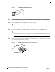
• Always grasp the LC connector housing to plug or unplug a fiber-optic cable.
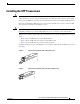
To cable the converter, follow these steps:
Step 1 Remove the dust plugs from the network interface cable LC connectors. Save the dust plugs for future
use.
Step 2 Inspect and clean the LC connector’s fiber-optic end-faces. Refer to the Tip below for a pointer to a
fiber-optic inspection and cleaning white paper.
Tip For complete information on inspecting and cleaning fiber-optic connections, refer to the white paper at
this URL:
http://www.cisco.com/en/US/tech/tk482/tk607/technologies_white_paper09186a0080254eba.shtml
Step 3 Remove the dust plugs from the SFP transceiver optical bores.
Step 4 Immediately attach the network interface cable LC connector to the SFP transceiver.
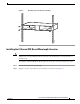
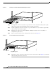
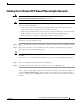
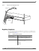
Figure 9 shows a sample cabling scheme for the 2-channel wavelength converter. In this example, you
would use 1000BASE-LX/LH SFPs to interface between the module and the 2-channel wavelength
converter, and you would use CWDM SFPs to interface from the 2-channel wavelength converter to the
network.