
Installation Guide


14
Cisco 2-Channel SFP-Based Wavelength Converter Installation Note
78-16648-01
Installing the SFP Transceivers
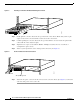
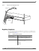
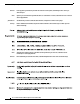
Figure 7 SFP Module with a Bale-Clasp Latch
To install an SFP transceiver, follow these steps:
Step 1 Attach an ESD-preventive wrist strap to your wrist and to the ESD ground connector or a bare metal
surface on your chassis.
Step 2 Remove the SFP transceiver module from its protective packaging.
Note Do not remove the optical bore dust plugs until you are directed to do so later in the procedure.
Step 3 Check the label on the SFP transceiver body to verify that you have the correct model for your network.
Step 4 Find the send (TX) and receive (RX) markings that identify the top side of the SFP transceiver.
Note On some SFP transceivers, the TX and RX marking might be replaced by arrowheads pointing
from the SFP transceiver connector (transmit direction or TX) and toward the connector (receive
direction or RX).
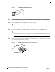
Step 5 Position the SFP transceiver in front of the socket opening.
Step 6 Insert the SFP transceiver into the socket until you feel the SFP transceiver module connector snap into
place in the socket connector. (See Figure 8.)
Figure 8 Inserting an SFP Transceiver into a Module Socket
63067
94126