
Installation Guide

10
Cisco 2-Channel SFP-Based Wavelength Converter Installation Note
78-16648-01
Installing the 2-Channel SFP-Based Wavelength Converter
Installing the 2-Channel SFP-Based Wavelength Converter
The following sections provide installation procedures for the 2-Channel SFP-Based Wavelength
Converter:
• Required Tools, page 10
• Installing the 2-Slot Chassis (CWDM-CHASSIS-2=), page 10
• Installing the 2-Channel SFP-Based Wavelength Converter, page 11
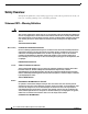
Required Tools
You will need these tools to install the 2-Channel SFP-Based Wavelength Converter:
• Number 2 Phillips screwdriver for the 10-32 or the 12-24 chassis installation screws.
• Wrist strap or other personal grounding device to prevent ESD occurrences.
• Antistatic mat or antistatic foam to place the equipment on.
• Fiber-optic end-face cleaning tools and inspection equipment. For complete information on
inspecting and cleaning fiber-optic connections, refer to the white paper at this URL:
http://www.cisco.com/en/US/tech/tk482/tk607/technologies_white_paper09186a0080254eba.shtml
• Level (optional)
• Tape measure (optional)
Installing the 2-Slot Chassis (CWDM-CHASSIS-2=)
Note Ensure that you install the 2-slot chassis in the same rack as your system or an adjacent rack to your
system so that you can connect all cables between your 2-Channel SFP-Based Wavelength Converter and
your system.
Caution When performing the following procedures, wear a grounding strap to avoid ESD damage to the
2-Channel SFP-Based Wavelength Converter. Some platforms have an ESD connector for attaching the
wrist strap.
To mount the 2-slot chassis in an equipment rack, follow these steps:
Step 1 Remove the 2-slot chassis from the shipping packaging.
Step 2 Position the 2-slot chassis in the rack in which you are going to install it. Align the mounting holes in
the chassis L brackets with the mounting holes in the equipment rack to ensure that the 2-slot chassis is
mounted straight and level. Use a level or tape measure to verify that the chassis is mounted level in the
rack.
Step 3 Secure the 2-slot chassis by using four (two per side) 12-24 x 3/4-inch screws or four 10-32 x 3/4-inch
screws. Thread the screws through the elongated holes in the L bracket and into the threaded holes in the
mounting post. (See Figure 2.)