Installation Guide
Manuals
Brands
Cisco Manuals
Broadband Nodes
Cisco Compact Dual Output Node A90075
11
12
13
14
15
16
17
18
19
20
Intro
duction
1-7
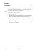
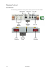
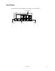
Block Diagram
The f
ollow
ing
is a
block
diagr
am of
the
optic
al re
verse t
ransm
itter.
Test Point
O
E
RTx
RF input
Opt. Out
Pilot
Gen.
µP
Control & LEDs
1
...
...
17
18
19
20
21
...
...
30