
Installation Guide

Introduction
1-5
Overview, Continued
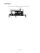
Panel Functions
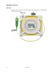
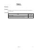
The following table lists the functions of the front panel indicators on the optical
reverse transmitter.
Description
Function
MODE LED
Green/OFF
Indicator
Green: Transmitter is working on the
Burst mode
OFF: Transmitter is working on the
Normal mode
LASER LED
OFF/Green/Yellow
/RED Indicator
OFF: Laser is switched off
Green: Laser is switched on
Yellow: Laser aging - The laser is
aged and uses more current than it
did when it was installed. The
transmitter should be replaced as
soon as possible
Red: Laser failure - The laser does
not function. The transmitter must be
replaced Immediately
PILOT LED
OFF/Green/Yellow
Indicator
OFF: The pilot tone is switched off or
laser is switch off
Green: The pilot tone is switched on
and set to standard level
Yellow: The pilot tone is switched on
and not set to standard level
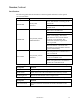
The following table lists other functions of the optical reverse transmitter front panel.
Description
Function
Push Buttons
Adjust the input level and pilot level
Mode Switch
Switch the mode of the transmitter between burst/normal.
Mounting Screw
Mounts the transmitter in the compact node.
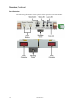
The following table lists the functions of the optical reverse transmitter rear panel.
Description
Function
8-Pin Connectors
Provides electrical connections from the transmitter to the
node