LAN Baseline Architecture Overview—Branch Office Network Americas Headquarters Cisco Systems, Inc. 170 West Tasman Drive San Jose, CA 95134-1706 USA http://www.cisco.
ALL DESIGNS, SPECIFICATIONS, STATEMENTS, INFORMATION, AND RECOMMENDATIONS (COLLECTIVELY, "DESIGNS") IN THIS MANUAL ARE PRESENTED "AS IS," WITH ALL FAULTS. CISCO AND ITS SUPPLIERS DISCLAIM ALL WARRANTIES, INCLUDING, WITHOUT LIMITATION, THE WARRANTY OF MERCHANTABILITY, FITNESS FOR A PARTICULAR PURPOSE AND NONINFRINGEMENT OR ARISING FROM A COURSE OF DEALING, USAGE, OR TRADE PRACTICE.
C O N T E N T S LAN Services Overview 1 Branch LAN Design Considerations 2 Multilayered Branch Architecture 3 Services 4 Access Layer 5 Layer 2 versus Layer 3 at Access Layer 6 VLANs and Spanning Tree Protocol 9 Voice and Data VLANs 10 Security 11 QoS 14 Distribution Layer 15 High Availability 15 Scalability 17 Additional Services 18 Conclusion 18 References 19 LAN Baseline Architecture Overview—Branch Office Network OL-11333-01 iii
Contents LAN Baseline Architecture Overview—Branch Office Network iv OL-11333-01
LAN Baseline Architecture Overview—Branch Office Network This document provides guidance on how to design a local area network (LAN) for a Business Ready Branch or autonomous Business Ready Office where corporate services such as voice, video, and data are converged onto a single office network. This document provides an overview of LAN architecture.
Branch LAN Design Considerations Branch LAN Design Considerations Branch LAN infrastructure provides connectivity to the end devices to access the corporate network. In a small office and even a medium-sized branch office, the resources are typically located at the corporate headquarters and accessed through a wide area network (WAN) of varying bandwidth.
Multilayered Branch Architecture Multilayered Branch Architecture Typically, the branch LAN infrastructure is logically similar to the campus LAN infrastructure. However, because of the differences in scalability, high availability, manageability, and cost considerations, the network devices deployed can be different in branch and campus environments.
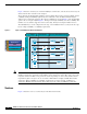
Multilayered Branch Architecture Figure 1 shows the various layers of a branch multilayered architecture, and also shows various ways in which a branch office network can be designed. The architecture should be highly available as well as scalable. Based on the products available, and the scalability and high availability requirements, the architecture can be modified without losing the distinct services offered by each layer. The various possibilities are shown in Figure 1.
Multilayered Branch Architecture Figure 2 Services at Various Layers of a Branch Architecture WAN ISR at the edge Edge Services Services Distribution Access 29xx or 35xx Access Switches AP Access Point Access Point 180054 Services Edge layer services include WAN, firewall, intrusion detection and prevention, and voice. Edge layer services and details about the edge design are not covered in this document, but are available at the following URL: http://wwwin.cisco.com/ios/systems/ese/.
Multilayered Branch Architecture • Network Admission Control (NAC) to protect against viruses With many of these services provided at the access layer, the best design practice should integrate all these services seamlessly either at Layer 2 or Layer 3 access. The following sections provide more details of the considerations that go into the design of an access layer and the various elements of the access layer.
Multilayered Branch Architecture Figure 4 Traditional Highly-Available LAN Design Core Or Edge Layer 3 Loop Distribution Access Point 180053 Layer 2 Access The Layer 2 access switch is connected to both the distribution switches, and the distribution switches are connected together by a trunked EtherChannel.
Multilayered Branch Architecture Figure 5 Highly-Available LAN Design with No Layer 2 Loops Core Or Edge Layer 3 Stackwise switches Distribution Stack Ring Layer 2 Access Point 180057 Access This topology uses stackable switches at the distribution layer instead of two distribution switches running Hot Standby Routing Protocol (HSRP). This topology is highly available and scalable. In this topology, the Layer 3 redundancy is built into the stack.
Multilayered Branch Architecture Figure 6 Layer 3 at the Access Layer Core Or Edge Distribution Layer 3 Access AccessPoint Note 180055 Layer 2 It is quite possible that sub-second convergence under failover scenarios is achievable with both EIGRP and OSPF routing protocols. The testing has not been done. Layer 3 at the access is not recommended in the branch office designs because of the following reasons: • Higher costs involved with deploying such a solution.
Multilayered Branch Architecture VLANs help to segregate the traffic from different endpoints. For example, voice, video, and data can be segregated by putting the devices into different VLANs. VLANs are also widely used to segregate different users. The proliferation of VLANs results in the various types of spanning tree protocols; Spanning Tree Protocol (STP) prevents loops from being formed when switches or bridges are interconnected by multiple links. Spanning tree protocols such as IEEE 802.
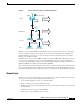
Multilayered Branch Architecture Figure 7 Data and Voice VLAN on a Switch Port 3 IP 1 2 1: IP Phone + Standard Desktop 2: Access Point 3: Uplink to router Voice VLAN Data VLAN 180060 Switch Port Role The first VLAN, called the data VLAN, is sent and received untagged. The second VLAN, called the voice VLAN, is sent tagged with a dot1q header and a voice VLAN to which it belongs. However, the switch port is not a trunk port. The tagged packet comes from the IP phone.
Multilayered Branch Architecture For more information on how to enable these features on Cisco Catalyst 4500 Series Switches, refer to the configuration guide at the following URL: http://www.cisco.com/en/US/products/hw/switches/ps4324/products_installation_and_configuration_g uides_list.html For more information on how to enable these features on Cisco Catalyst 6500 Series Switches, refer to the configuration guide at the following URL: http://www.cisco.
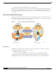
Multilayered Branch Architecture Figure 8 Authenticating the End User using 802.1x 2 1 3 RADIUS server IP 4 2 1 Authentication Response 2 2 1 3 4 Authentication Request RADIUS server 2 Authentication Response 1. End User with a supplicant 2. Access Point 3. Authenticator Voice VLAN Data VLAN 180061 Authentication Request The authentication process consists of exchanges of Extensible Authentication Protocol (EAP) messages between the supplicant and the authentication server.
Multilayered Branch Architecture signature set prior to gaining access to the network. If the client requires a signature update, NAC directs it to the appropriate resources to complete the update. One example in which NAC accomplishes this is through placing the client into a quarantined network segment until disinfection is completed. More details will be documented in a future document. QoS During congestion in the network, traffic is delivered on a best effort basis.
Multilayered Branch Architecture Figure 9 Trust Boundary Trust Boundary Permit or Mark QoS To Core or Branch Edge IP Access Layer Distribution Layer Partially trusted device Server Farm Untrusted Device Voice VLAN Data VLAN 180059 Trusted Device Distribution Layer The distribution layer provides the following services: • High availability • Scalability • An aggregation point to deploy additional services if required High Availability Typically, high availability designs at the Layer 3 level
Multilayered Branch Architecture Figure 10 Multilayered Branch Architecture using External Distribution Switches Option 1 Option 2 WAN ISR at the edge WAN Edge Stackable Switch Cross Stack Ether-channel Distribution Cross Stack connection Access 29xx or 35xx Access Switches 29xx or 35xx Access Switches Access Point Access Point Access Point 180063 AP Access Point As shown in Figure 10, using external distribution switches, Option 1 is a single chassis solution at the distribution layer t
Multilayered Branch Architecture • Layer 3 failure can take up to three seconds to converge under failure conditions. If the applications used need significantly less convergence times, then other options (option 1) have to be considered. In addition to high availability, it is possible to configure the switches to load balance the traffic on the EtherChannels.
Conclusion LAN ports available on the edge router. The Ethernet interfaces embedded in the ISR do not support switched virtual interfaces (SVIs). In addition, EtherChannels, LACP, and PAgP are not supported on the embedded Ethernet interfaces on the ISR. EtherChanneling and SVIs are supported only on network module-based Ethernet switches, which plug into ISRs to provide Catalyst switch features.
References network, when they are connected either directly or via the Cisco IP phone. Additional services can be deployed or enabled as they become available without having to redesign the network for the foreseeable future. References • Smart Ports— http://wwwin-tools.cisco.com/sales/go/salesrack/solutions/enterprise/architecture/campus/smartpo rts • Cisco AVVID Network Infrastructure Enterprise Quality of Service Design Guide— http://www.cisco.
References LAN Baseline Architecture Overview—Branch Office Network 20 OL-11333-01