
White Paper


© 2012 Cisco and/or its affiliates. All rights reserved. This document is Cisco Public Information. Page 37 of 55
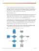
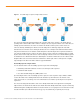
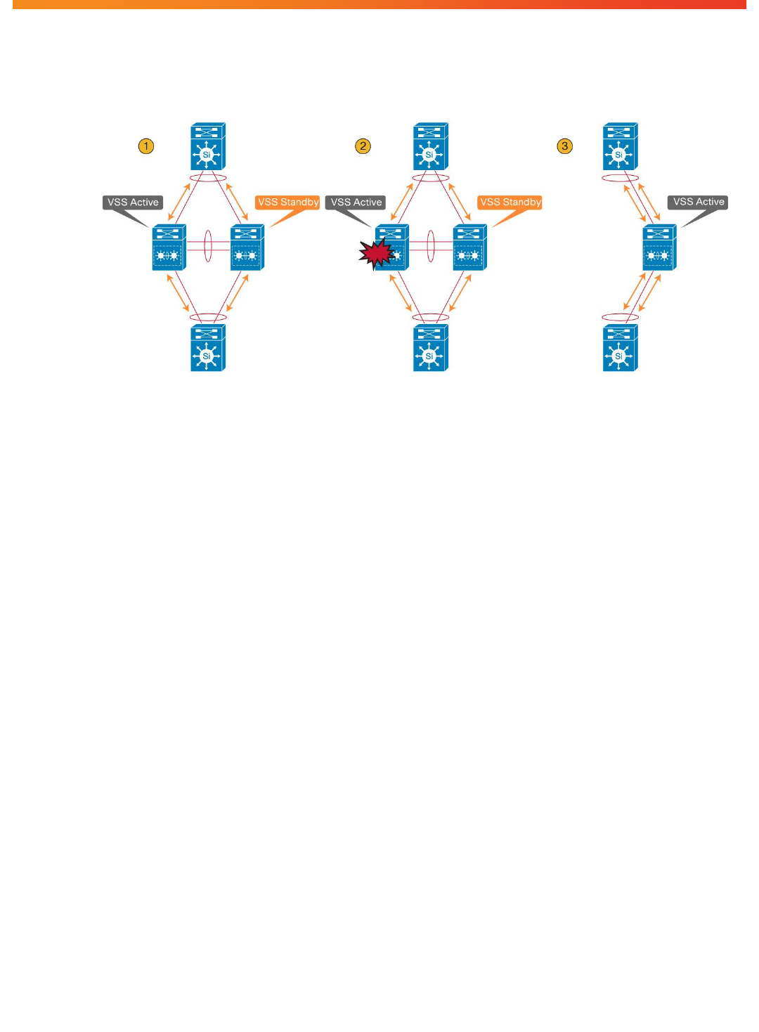
Figure 21. Three Main Stages of Supervisor Engine Switchover Event
The effect on the data path is illustrated in Figure 26, using three main stages. In Stage 1, the virtual switch is
operating under normal conditions with no failures. In Stage 2, the active supervisor failure occurs. At this time, the
standby supervisor transitions to the active role and all of the modules from the previous active chassis are
removed, effectively eliminating these interfaces from the data path. The third stage depicts all of the traffic
transitioned to the new active chassis. During the transition, there is a disruption to the traffic that must transition
away from the failed chassis. The duration of traffic disruption is determined by the time required to transition the
role of the hot-standby supervisor engine to the active supervisor engine, and for the neighboring device to modify
its path selection to the newly active chassis. If the vast majority of interfaces in the Cisco Virtual Switching System
are multichassis Cisco EtherChannel links, this data disruption should have minimal effect on the network, and the
disruption will be sub-second. Packets that are handled in the software path, however, will experience a slightly
longer disruption. This failover should be similar to a typical SSO failure.
Hot-Standby Supervisor Engine Failure
You can detect the failure of the hot-standby supervisor engine in the following ways:
●
Redundancy framework heartbeats sent across the VSL by the active supervisor
●
Full VSL link-down situation
●
Cisco Generic Online Diagnostics (GOLD) failure event
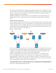
Upon detecting the failure of the hot-standby supervisor engine, the active supervisor engine simulates an OIR
event for all modules in the standby virtual switch. This simulation is performed because the modules on the
remote chassis have no connectivity, since VSL communication to the modules is proxied by the local supervisor-
engine CPU.
The effect on the data path is that all line cards on the standby virtual switch are brought down. Assuming that
adjacent devices are dual-homed to both the active virtual switch and standby virtual switch, only those flows being
forwarded through the standby virtual switch are affected. The time to recovery depends on the mechanism used to
detect the link failure (Cisco EtherChannel technology, Layer 3 load balancing, or Spanning Tree Protocol).