White Paper Cisco Catalyst 6500 Series Virtual Switching System White Paper December, 2012 © 2012 Cisco and/or its affiliates. All rights reserved. This document is Cisco Public Information.
Contents Introduction .............................................................................................................................................................. 3 Cisco Catalyst 6500 Series Virtual Switching System: An Overview .................................................................. 3 Cisco Catalyst 6500 Series Virtual Switching System Architecture .................................................................... 3 Virtual Switch Link .......................................
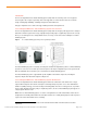
Introduction The Cisco Catalyst 6500 Series Virtual Switching System (VSS) allows the clustering of two or more physical chassis together into a single, logical entity. This technology allows for enhancements in all areas of network design, including high availability, scalability, management, and maintenance. This paper explains the Cisco VSS technology, including its benefits and requirements.
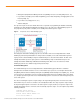
● Management (Simple Network Management Protocol [SNMP], Telnet, Secure Shell [SSH] Protocol, etc.) ● Layer 2 Protocols (bridge protocol data units [BPDUs], protocol data units [PDUs], Link Aggregation Control Protocol [LACP], etc.) ● Layer 3 Protocols (routing protocols, etc.
Local switch operational role: Virtual Switch Active Peer switch number: 2 Peer switch operational role: Virtual Switch Standby VSS-Sup720#show switch virtual redundancy My Switch Id = 1 Peer Switch Id = 2 Last switchover reason = none Configured Redundancy Mode = sso Operating Redundancy Mode = sso Switch 1 Slot 6 Processor Information: ----------------------------------------------Current Software state = ACTIVE Uptime in current state = 6 weeks, 5 days, 16 hours, 19 minutes Image Version = Cisco IOS Soft
Router MAC Addresses When a virtual switch boots up and transitions to an active state, it assigns all its Layer 3 interfaces with a MAC address. From a default configuration, the MAC address is derived from an EEPROM memory device located on the Catalyst 6500 chassis itself. Whichever supervisor is elected to the active role will provide the system MAC address for the VSS. The EEPROM is programmed in the factory and contains range of unique MAC addresses.
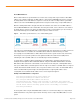
Virtual Switch Link The Cisco Catalyst 6500 Series Virtual Switching System consists of two Cisco Catalyst 6500 chassis. In order to bond the two chassis together into a single, logical node, special signaling and control information must be exchanged between the two chassis in a timely manner. To facilitate this information exchange, a dedicated link is used to transfer both data and control traffic between the peer chassis. This link is referred to as the virtual switch link (VSL).
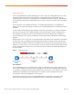
Virtual Switch Link Initialization The system must bring the VSL online before activating the Cisco Virtual Switching System. The initialization sequence consists of the following steps: Figure 5. ● VSL Initialization VSL initialization The supervisor CPU determines which ports local to its chassis form members of the VSL, the configuration file is preparsed to extract the appropriate VSL commands and their associated interfaces.
An example of how configuration checking may force the system into RPR mode is provided in the following output: *Jun 29 14:05:44.731: %VSLP-SW2_SP-5-RRP_ROLE_RESOLVED: Role resolved as ACTIVE by VSLP *Jun 29 14:05:44.735: %VSL-SW2_SP-5-VSL_CNTRL_LINK: vsl_new_control_link NEW VSL Control Link 5/4 *Jun 29 14:05:44.735: %VSL-SW2_SP-2-VSL_STATUS: === VSL is UP *Jun 29 14:08:22.
Hardware and Software Requirements The Virtual Switching System supports a specific subset of hardware compared to what is supported in a standalone configuration or non-VSS configuration. Therefore it is important to understand these requirements when planning the configuration of a VSS. Supervisor Engines The initial release of the Virtual Switching System on the Cisco Catalyst 6500 was in January 2008, with the Supervisor Engine 720-10G.
Forwarding Engine The Cisco Catalyst 6500 can be configured with a single centralized forwarding engine. In this case, the Policy Feature Card (PFC) is the sole forwarding engine for the system. Optionally, the Cisco Catalyst 6500 can be configured with distributed forwarding engines to provide higher scalability and performance. In a distributed forwarding configuration, the line cards are populated with the Distributed Forwarding Daughter Cards (DFCs).
Example for Sup2T: vss#show platform hardware pfc mode PFC operating mode : PFC4 Configured PFC operating mode : None Additionally, as an optional configuration, the supervisor engines of both chassis may prenegotiate their modes to be in XL-mode or non-XL-mode. This is useful if one wants to help ensure that a VSS running in PFC3C-XL or PFC4-XL mode will not negotiate to a non-XL mode in the event a non-XL line card is inserted into the system.
Other Supported Modules Supported interface modules that can coexist within a Cisco Virtual Switching System-enabled chassis include all CEF720 modules (WS-X6700 series). These modules can also support either a centralized forwarding card (CFC) or a DFC. If a DFC is installed, it must be compatible with the supervisor PFC operating mode (for example, PFC3C mode for the Supervisor Engine 720-10G and PFC4 mode for the Superviosr Engine 2T).
By configuring at least one of the supervisor uplink ports as a VSL port, the system will be able to initialize the VSL without having to initialize any other line cards. Therefore, it is beneficial and recommended to use at least one of the supervisor module 10 Gigabit Ethernet uplink ports for the VSL. Two-Port VSL Using Supervisor-Engine Uplinks In this scenario, the two members of the Cisco Virtual Switching System are connected through a 2-port VSL EtherChannel.
Figure 8. Quad-Sup Uplink Forwarding VSL Configuration Quad-Sup Uplink Forwarding VSL design using all 10 Gigabit ports on the supervisor modules: ● Maintains 20 Gbps VSL bandwidth in the event of a supervisor failure ● Maintains at least one locally attached VSL port to the active supervisor, in the event of a supervisor module failure ● Requires no additional line cards If additional bandwidth is needed for the VSL, additional 10 Gigabit ports from supported line cards can be used.
Another example of multiple Cisco Virtual Switching System domains is in the area of Layer 2 adjacent WAN deployments. It may be a requirement for the business or the applications that a routed Layer 3 WAN connection may not be possible requiring a Layer 2 connection between two disparate geographic sites, yet still providing link redundancy at the same time.
With the Supervisor Engine 2T, additional hash schemes supporting the source and destination VLAN are supported for up to 19 total options: VSS2T(config)# port-channel load-balance ? dst-ip Dst IP Addr dst-mac Dst Mac Addr dst-mixed-ip-port Dst IP Addr and TCP/UDP Port dst-port Dst TCP/UDP Port mpls Load Balancing for MPLS packets src-dst-ip Src XOR Dst IP Addr src-dst-mac Src XOR Dst Mac Addr src-dst-mixed-ip-port Src XOR Dst IP Addr and TCP/UDP Port src-dst-port Src XOR Dst TCP/UDP Port
Adaptive Load Balancing The addition or removal of a member port from a Cisco EtherChannel interface has always led to a varied amount of traffic loss for customers. The current generation of port ASICs uses a 3-bit Result Bundle Hash (RBH) value from the PFC or DFC result to index into a load register. This allows a packet to be transmitted if the corresponding bit is set. When a new port is added or deleted, the load value is reset on all the ports.
4 Po4(SU) PAgP Gi1/5/3(P) Gi2/5/3(P) Last applied Hash Distribution Algorithm: Adaptive Although this new load-distribution algorithm requires configuration for regular Cisco EtherChannel and multichassis Cisco EtherChannel interfaces, it is the default load-distribution algorithm used on the virtual switch links. Multichassis Cisco EtherChannel Links The multichassis Cisco EtherChannel interface spans more than a single physical switch (Figure 11).
For traffic that must be flooded on the VLAN (broadcasts, multicasts, and unknown unicasts), a copy is sent across the VSL to be sent out any single-homed ports belonging to the VLAN. Because the first chassis will have sent a copy out one of the multichassis Cisco EtherChannel ports, packets received from the VSL are not sent out of another multichassis Cisco EtherChannel port.
If there is a misconfiguration in switch IDs (when both switches have the same switch ID), the formation of the VSL will fail on initialization. When the two chassis are being brought up as a single Cisco Virtual Switching System, the VSL initialization handshake verifies that the switch IDs of the two chassis do not match. If the switch ID is found to be in conflict, the VSL will not become active.
Step 2. Configure the VSL port channel and member ports. Choose unique port-channel IDs for each chassis to form the VSL and configure them with the corresponding switch ID, using the following commands: VSS-sw1#conf t VSS-sw2#conf t Enter configuration commands, one per line. End with CNTL/Z. Enter configuration commands, one per line. End with CNTL/Z.
Four actions occur when you issue this command: ● The running configuration of the individual switch is converted into a three-level virtual switch interface notation. Two-level interface configurations (such as 10 GigabitEthernet 5/4) are converted into three-level interfaces (such as 10 GigabitEthernet 1/5/4 in Switch 1 and 10 GigabitEthernet 2/5/4 in Switch 2). ● The startup configuration is updated with the three-number notation.
Although not required, it is possible to verify that all modules have been automatically provisioned and their module types stored in the configuration by issuing the following command on the active virtual switch: VSS#sh run | begin module provision module provision switch 1 slot 1 slot-type 254 port-type 31 number 2 port-type 61 number 1 port-type 60 number 2 virtual-slot 17 slot 2 slot-type 148 port-type 60 number 4 virtual-slot 18 slot 3 slot-type 147 port-type 61 number 48 virtual-slot 19 ! module prov
In addition the startup configurations will be updated with the new merged configurations. Do you want proceed? [yes/no]: yes Merging the standby VSL configuration. . . Building configuration... [OK] This command prompts you to accept all standby virtual switch VSL-related configurations, and also updates the startup configuration with the new merged configurations. Note that only VSL-related configurations are merged with this step; all other configurations will be lost and require manual intervention.
If a switchover occurs and switch 2 becomes the active virtual switch, the console becomes active on that supervisor engine.
bootdisk: sw2-slot5-sup-bootflash: sw2-slot7-dfc-bootflash: sw2-slot8-dfcbootflash: You can still use the existing file-system naming scheme, but you need to determine the role of the switch (active or standby) before you access the file systems. Reloading the Cisco Virtual Switching System and Its Members It may sometimes be desirable to reload the entire system or to reset individual members of the Virtual Switching System. You can perform these tasks through the console of the active virtual switch.
High Availability Central to the high-availability model of a Cisco Virtual Switching System are the concepts of NSF/SSO and RPR. The intricacies of these protocols are beyond the scope of this paper; you can find more information on these protocols in the Catalyst 6500 documentation materials as well as in the following white paper: “Non-Stop Forwarding and Stateful Switchover on the Catalyst 6500” http://www.cisco.com/en/US/prod/collateral/switches/ps5718/ps708/prod_white_paper0900aecd801c5cd7.
Compiled Thu 31-May-07 02:23 by kchristi BOOT = sup-bootdisk:s72033-adventerprisek9_wan_dbg-vz.
local chassis. From the local chassis perspective, whichever supervisor boots first will become the “In-chassis Active” supervisor, while the second supervisor will be become the “In-chassis Standby” supervisor. See Figure 14 Figure 14. Virtual Switching System with Quad-Sup Uplink Forwarding With the In-chassis Standby supervisor fully booted, the uplink ports are fully operational. They can be used as part of the VSL port-channel interfaces or other connectivity, just like ports on any other line card.
During the local chassis reload, the line cards will also reload. For devices connected to the Virtual Switching System in a dual-homed manner using a multi-chassis EtherChannel connection or using Layer 3 Equal Cost Multipath links, only the interfaces attached to the chassis performing the reload will be affected.
The only requirement to support Quad-Sup Uplink Forwarding is that both supervisor modules must be configured to boot the 12.2(33)SXI4 or newer software version. The installation process for the redundant supervisor assumes that the in-chassis active supervisor is already configured and converted to the virtual switching mode. Figure 16 shows the console output stage.
Figure 17. Abbreviated Output From the “show switch virtual redundancy” CLI with Quad-Sup Uplink Forwarding Enabled Configuration Synchronization When the redundancy-framework progression between the active supervisor engine and standby supervisor engine is reached, the configuration is synchronized between active virtual switch and standby virtual switch.
vss(config-vs-domain)#switch 1 priority 110 *Jul 7 08:59:11.913: %VSLP-SW1_SPSTBY-5-RRP_RT_CFG_CHANGE: Configured priority value is different from operational value. Change will take effect after config is saved and switch is reloaded. vss(config-vs-domain)#switch 2 priority 100 vss(config-vs-domain)#^Z vss# Notice from this configuration that the higher-priority value (110) assumes the active virtual switch role and the default priority is set to 100 (Figure 18). Figure 18.
Figure 19. Virtual Switch Preemption You should enable Switch Preemption only on the switch that has the higher switch priority. With the following command, you can enable this function under the virtual switch configuration mode. You can specify an optional timer value from 5 to 20 minutes, where this number represents the number of minutes the current active virtual switch waits after it establishes communication with the peer standby virtual switch through the VSL.
Typically, in a standalone environment, these First Hop Redundancy Protocols (FHRPs) are required to provide a single default gateway that is both redundant and highly available. These protocols typically designate an active forwarder for a given pair of Layer 3 interfaces by using respective hello protocols. Additionally, a separate instance of these hello protocols is run for each pair of interfaces for which the FHRP is configured.
Figure 21. Three Main Stages of Supervisor Engine Switchover Event The effect on the data path is illustrated in Figure 26, using three main stages. In Stage 1, the virtual switch is operating under normal conditions with no failures. In Stage 2, the active supervisor failure occurs. At this time, the standby supervisor transitions to the active role and all of the modules from the previous active chassis are removed, effectively eliminating these interfaces from the data path.
Upon detecting that the interface connected to the standby virtual switch has failed, traffic resorts to using the link to the active supervisor engine. Those data flows passing through the active virtual switch are not affected. The control plane is not affected because the control-plane functions remain on the active supervisor engine on the active virtual switch. The control plane experiences a removal of all of the standby virtual switch interfaces.
Figure 23. Link Fail Convergence This link failure causes the RBH values to be redistributed among the remaining multichassis Cisco EtherChannel link ports in the local chassis, which is the same as a link failure in a standard Cisco EtherChannel link using a standalone Cisco Catalyst 6500. The endpoint (host, switch, router, etc.) on the other end of the multichassis Cisco EtherChannel link detects the link failure, and adjusts its load-balancing algorithms to avoid the failed link.
The control protocols managing the Cisco EtherChannel link (PAgP or LACP) continue to originate from the active supervisor engine and are sent out of the standby virtual switch ports through the VSL. The endpoint (host, switch, router, etc.) on the other end of the multichassis Cisco EtherChannel link detects the link failure and adjusts its load-balancing algorithms to avoid the failed link. Availability is not affected for those data flows that do not use the failed link.
In some circumstances, this configuration may not be possible.
Upon the detection of VSL going down on Switch 2, the switch will immediately transmit a PAgP message on all port channels enabled for Enhanced PAgP dual-active detection, with a Type-Length-Value (TLV) containing its own Active ID = 2. When the access switch receives this PAgP message on any member of the port channel, it detects that it has received a new active ID value, and considers such a change as an indication that it should consider Switch 2 to be the new active virtual switch.
Figure 27. Dual-Active Detection Using IP-BFD Bidirectional Forwarding Detection (BFD) assists in the fast detection of a failed VSL, natively bringing in the benefits that BFD offers, such as subsecond timers and pseudo-preemption. To take advantage of this feature, you must first configure BFD on the selected interfaces that will be participating in IP-BFD dual-active detection, noting that these interfaces must be directly connected to each other: vss#conf t Enter configuration commands, one per line.
Note that by configuring these commands, static routes are automatically added for the remote addresses and are installed in the Routing Information Base (RIB) only if a dual-active scenario occurs. As a result, no packets are forwarded between the switches through the heartbeat interfaces until the VSL is brought down.
dual-active fast hello end Once Fast Hello has been configured, the existing configuration on the interface will be automatically removed and will only be restricted for Fast Hello configurations. Also, UDLD will be disabled on Fast Hello pairs.
*Jun 26 16:06:37.297: %VSLP-SW2_SPSTBY-3-VSLP_LMP_FAIL_REASON: Port 5/5: Link down *Jun 26 16:06:37.297: %VSL-SW2_SPSTBY-2-VSL_STATUS: -======== VSL is DOWN ========*Jun 26 16:06:37.301: %PFREDUN-SW2_SPSTBY-6-ACTIVE: Initializing as Virtual Switch ACTIVE processor *Jun 26 16:06:37.353: %SYS-SW2_SPSTBY-3-LOGGER_FLUSHED: System was paused for 00:00:00 to ensure console debugging output. *Jun 26 16:06:37.
Campus 3.0 Virtual Switching System Design Guide http://www.cisco.com/en/US/docs/solutions/Enterprise/Campus/VSS30dg/campusVSS_DG.html. Quality of Service Quality of service (QoS) handling on the Cisco Catalyst 6500 Series switches can be separated into two distinct areas of responsibility: port-based QoS features and forwarding-engine (PFC or DFC) features. Both areas operate together to help ensure differentiated servicing of traffic throughout the system.
no ip address switch virtual link 2 mls qos trust cos end vss#conf t Enter configuration commands, one per line. End with CNTL/Z.
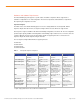
3 100[1] 100[2] 100[3] 100[4] WRED disabled queues: queue thresh cos-map --------------------------------------1 1 0 1 2 1 1 3 1 4 2 1 2 2 2 3 4 2 3 2 4 3 1 6 7 3 2 3 3 3 4 4 1 5 Queueing Mode In Rx direction: mode-cos Receive queues [type = 2q4t]: Queue Id Scheduling Num of thresholds ----------------------------------------01 WRR 04 02 WRR 04 WRR bandwidth ratios: 10[queue 1] 90[queue 2] queue-limit ratios: 80[queue 1] 20[queue 2] queue tail-drop-thresholds -------------------------1 70[1] 80[2] 90[3] 100
2 2 2 3 2 4 <…snip…> A restriction has been imposed, however, that does not permit you to modify QoS settings on the VSL ports in the initial release of software. Hence, you can modify only the default queue, drop threshold, and buffer depth settings. vss(config)#int te2/5/4 vss(config-if)#priority-queue cos-map 1 2 HWIF-QOS: QoS configs are not allowed on VSL Portgroup Additionally, policy maps used for classification or policing are also forbidden on the VSL and its respective members.
VSS#sh interfaces tenGigabitEthernet 1/5/4 capabilities | include QOS QOS scheduling: rx-(8q4t), tx-(1p7q4t) QOS queueing mode: rx-(cos,dscp), tx-(cos,dscp) Applying Policies Classification or policing policies are applied to the system through the Modular QoS CLI (MQC) mechanisms, which use class maps and policy maps. Each policy map can use multiple class maps to make up a policy map, and you can define these policy classes for different types of traffic flows.
The policing function is typically handled by the ingress forwarding engine (either PFC or DFC). A critical restriction to implementing aggregate policers in a Cisco Virtual Switching System environment is the current lack of distributed aggregate policing capabilities across different forwarding engines. That is, if a policer is required to span across multiple forwarding engines, each forwarding engine keeps track of its own token-bucket quota and hence generally results in the under-policing of traffic.
As a result, only flows that always arrive on the same forwarding engine are policed correctly; otherwise they are underpoliced.
Router ACLs Router ACLs refers to all ACLs that are applied to interfaces that also have an IP address specified, including Layer 3 physical routed interfaces, Layer 3 SVIs, as well as port-channel interfaces. Directional by nature, RACLs apply only to traffic that is routed through those specific interfaces. In a Cisco Virtual Switching System environment, RACLs do not change significantly, since they can be applied to all Layer 3 interfaces across the entire system (on Switch 1, Switch 2, or both).
In a Cisco Virtual Switching System environment, VACLs do not change significantly, because they can be applied across VLANs that are local to a particular virtual switch as well as across the entire Cisco Virtual Switching System. Global TCAM show commands have also been extended to account for the switch keyword. Port-Based ACLs PACLs refers to those ACLs that are applied directly to a physical port that is also configured as a Layer 2 switchport.