SecGW Administration Guide, StarOS Release 17 Last Updated July 6, 2015 Americas Headquarters Cisco Systems, Inc. 170 West Tasman Drive San Jose, CA 95134-1706 USA http://www.cisco.
THE SPECIFICATIONS AND INFORMATION REGARDING THE PRODUCTS IN THIS MANUAL ARE SUBJECT TO CHANGE WITHOUT NOTICE. ALL STATEMENTS, INFORMATION, AND RECOMMENDATIONS IN THIS MANUAL ARE BELIEVED TO BE ACCURATE BUT ARE PRESENTED WITHOUT WARRANTY OF ANY KIND, EXPRESS OR IMPLIED. USERS MUST TAKE FULL RESPONSIBILITY FOR THEIR APPLICATION OF ANY PRODUCTS.
CONTENTS About this Guide ............................................................................................... vii Conventions Used .................................................................................................................................. viii Documents and Resources ......................................................................................................................ix Related Common Documentation ..........................................................
▀ Contents Access List ..................................................................................................................................... 34 Duplicate Session Detection .......................................................................................................... 34 Peer List ......................................................................................................................................... 34 Pre-fragment MTU .............................................
Contents ▀ Sample Basic wsg-service Configuration ...................................................... 63 WSG Context (StarOS) .......................................................................................................................... 64 Clear Traffic Interface – Primary ........................................................................................................ 64 Clear Traffic Interface – Backup..................................................................................
About this Guide This preface defines the Security Gateway, the organization of this guide and its document conventions. The Security Gateway (SecGW) is a StarOS product that runs in a VPC-VSM instance as a StarOS virtual machine (VM) on a Virtualized Services Module (VSM) in a Cisco ASR 9000 router. This guide assumes that Virtualized Packet Core for VSM (VPC-VSM) instances are already installed and running on one or more VSMs.
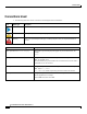
About this Guide ▀ Conventions Used Conventions Used The following tables describe the conventions used throughout this documentation. Icon Notice Type Description Information Note Provides information about important features or instructions. Caution Alerts you of potential damage to a program, device, or system. Warning Alerts you of potential personal injury or fatality. May also alert you of potential electrical hazards.
About this Guide Documents and Resources ▀ Documents and Resources Related Common Documentation The most up-to-date information for this product is available in the Release Notes provided with each product release.
About this Guide ▀ Contacting Customer Support Contacting Customer Support Use the information in this section to contact customer support. Refer to the support area of http://www.cisco.com for up-to-date product documentation or to submit a service request. A valid username and password are required to access this site. Please contact your Cisco sales or service representative for additional information.
Chapter 1 Security Gateway Overview This chapter contains general overview information about the Security Gateway (SecGW) running on an ASR 9000 Virtualized Service Module (VSM) as a VPC-VSM instance.
Security Gateway Overview ▀ Product Overview Product Overview The SecGW is a high-density IP Security (IPSec) gateway for mobile wireless carrier networks. It is typically used to secure backhaul traffic between the Radio Access Network (RAN) and the operator core network. IPSec is an open standards set that provides confidentiality, integrity, and authentication for data between IP layer peers. The SecGW uses IPSec-protected tunnels to connect outside endpoints.
Security Gateway Overview Product Overview ▀ Figure 2. VSM High Level Block Diagram The ASR 9000 services architecture encompasses how the platform interfaces with the services independent of where the service is actually instantiated.
Security Gateway Overview ▀ Product Overview The figure below shows the relationship between IOS-XR running on the ASR 9000 and StarOS running on the VSM. Figure 3. IOS-XR and VSM The 10GE interfaces on the SecGW virtual machines are visible as 10GbE interfaces on the ASR 9000. The ASR 9000 line card forwards IP traffic to VSM 10GbE ports. VSM Resource Mapping to VPC-VSM VMs There are four CPU sockets on the VSM. Each CPU supports multiple cores.
Security Gateway Overview Product Overview ▀ Table 1. Resource Assignments for VSM CPUs CPU Available Cores Crypto Device PCI Port ID VM vCPUs 0 16 (2–9, 42–49) 04:00.0 00.0.0 VM1 16 VM2 16 VM3 20 88:0.1 — — C2:0.0 VM4 20 — — 00.0.1 1 18 (11–19, 51–59) 45.00.0 42.0.0 42.0.1 48.0.0 48.0.1 2 20 (20-29, 60-69) 85:00.0 82:0.0 82:0.1 88:0.0 3 20 (30-39, 70-79) C5:00.0 C2:0.1 C8:0.0 C8:0.1 Only twelve PCI ports can be mapped to ASR 9000 line card traffic.
Security Gateway Overview ▀ Product Overview PCI Port ID CPU ASR 9000 TenG VPC Slot/Port VM Application IF C2:0.0 3 TenGx/y/z/9 1/10 VM4 Uplink C2:0.1 TenGx/y/z/10 1/11 Downlink C8:0.0 TenGx/y/z/11 1/1 Management C8:0.1 — — — Unused For all VMs except VM1, the NICs are allocated from the corresponding socket. But in VM1, the third NIC (42:0.0) is picked from a different socket.
Security Gateway Overview Product Overview ▀ SecGW Application The StarOS-based Security Gateway (SecGW) application is a solution for Remote-Access (RAS) and Site-to-Site (S2S) mobile network environments. It is implemented via StarOS as a WSG (Wireless Security Gateway) service that leverages the IPSec features supported by StarOS. SecGW delivers the S2S IP Encryption capabilities required in UMTS/HSPA and LTE 3GPP LTE/SAE network architectures.
Security Gateway Overview ▀ Product Overview Blacklist/Whitelist by IDi Rekey Traffic Overlap CRL fetching with LDAPv3 Sequence Number based Rekey IKE Call Admission Control (CAC) PSK Support for up to 1000 Remote Secrets Certificate Chaining RFC 5996 Compliance Duplicate Session Detection Extended Sequence Number Security Gateway as IKE Initiator Reverse Route Injection SecGW also supports Reverse Route Injection (RRI).
Security Gateway Overview ASR 9000 VSM IPSec High Availability ▀ ASR 9000 VSM IPSec High Availability This section briefly describes the IPSec High Availability (HA) capabilities for VSM service cards within an ASR 9000 For this release the ASR 9000 supports the following levels of High Availability Process Recovery VSM-to-VSM ICSR 1:1 Redundancy Chassis-to-Chassis ICSR Redundancy HA functions are triggered for the following events: Route Processor (RP) failure Virtual Machine (VM) failure VSM
Security Gateway Overview ▀ ASR 9000 VSM IPSec High Availability VSM-to-VSM ICSR 1:1 Redundancy In this redundancy scenario, Interchassis Session Recovery ICSR utilizes the Service Redundancy Protocol (SRP) implemented between two VSMs running separate instances of VPC-VSM/SecGW in the same ASR 9000 chassis. VSM card status data is exchanged between VPN managers on active and standby VSMs via SRP. SA data is also exchanged via SRP.
Security Gateway Overview Network Deployment ▀ Network Deployment SecGW supports the following network deployment scenarios: Remote Access (RAS) Tunnels Site-to-Site (S2S) Tunnels Remote Access Tunnels In a RAS scenario, a remote host negotiates a child SA with the SecGW and sends traffic inside the child SA that belongs to a single IP address inside the remote host. This is the inner IP address of the child SA. The outer IP address is the public IP address of the remote host.
Security Gateway Overview ▀ Packet Flow Packet Flow The figures below indicate traffic packet flows to and from the SecGW. Figure 7.
Security Gateway Overview Packet Flow ▀ Figure 8.
Security Gateway Overview ▀ Standards Standards Compliant RFC 1853 – IP in IP Tunneling RFC 2401 – Security Architecture for the Internet Protocol RFC 2402 – IP Authentication Header RFC 2406 – IP Encapsulating Security Payload (ESP) RFC 2407 – The Internet IP Security Domain of Interpretation for ISAKMP RFC 2408 – Internet Security Association and Key Management Protocol (ISAKMP) RFC 2409 – The Internet Key Exchange (IKE) RFC 2410 – Internet X.
Security Gateway Overview Standards ▀ Hashed Message Authentication Codes HMAC AES 128 GMAC HMAC AES 192 GMAC HMAC AES 256 GMAC Encryption Algorithms Diffie Hellman (DH) Group 19 DH Group 20 DH Group 21 DH Group 24 Certificates Digital Signature Algorithm (DSA) xAuth SecGW Administration Guide, StarOS Release 17 ▄ 25
Chapter 2 SecGW Service Creation This chapter describes the requirements and procedures for enabling the WSG (Wireless Security Gateway) service within StarOS. Enabling this service creates the SecGW.
SecGW Service Creation ▀ Prerequisites Prerequisites This section describes the requirements that must be met prior to configuring the SecGW. VPC-VSM Installation VPC-VSM must be running in a virtual machine on a VSM CPU within the ASR 9000 chassis. This guide does not describe the installation process. Refer to other ASR 9000 documentation for detailed installation instructions.
SecGW Service Creation SecGW Configuration Sequence ▀ SecGW Configuration Sequence The configuration sequence for enabling an SecGW is as follows: Create a crypto template with the desired IPSec functions. See Crypto Templates. Create Access Control Lists. See Access Control Lists. Enable and configure one or more WSG services. See WSG Service Configuration. Configure required IPSec features. See IPSec Configuration. For additional information, see the sample configurations provided in this guide.
SecGW Service Creation ▀ Crypto Templates Crypto Templates The StarOS CLI Crypto Template Configuration Mode is used to configure an IKEv2 IPSec policy. It includes most of the IPSec parameters and IKEv2 dynamic parameters for cryptographic and authentication algorithms. A security gateway service will not function without a configured crypto template. Only one crypto template can be configured per service.
SecGW Service Creation Crypto Templates ▀ You must create a crypto template before creating the WSG service that enables the SecGW. Important: Refer to the IPSec Reference for comprehensive information regarding the creation of crypto templates. A sample crypto template is shown below. It represents the output of the show crypto template tag template_name command.
SecGW Service Creation ▀ Access Control Lists Dead Peer Detection: Disabled Maximum CHILD_SA: 2 Overload Action: Ignore DOS Cookie Challenge: Disabled Dont Fragment: Copy bit from inner header Local Gateway: Not Set Remote Gateway: Not Set Access Control Lists IP access lists, commonly known as access control lists (ACLs), control the flow of packets into and out of the service.
SecGW Service Creation WSG Service Configuration ▀ WSG Service Configuration Configuring WSG Service enables SecGW functionality. The general configuration sequence includes: WSG Service Lookup Priority show Commands WSG Bulk Statistics Important: You must be logged into the StarOS CLI of a VPC-VSM instance to execute the commands described below. Important: For complete information on CLI commands described below, see the Command Line Interface Reference.
SecGW Service Creation ▀ WSG Service Configuration Deployment Mode A given instance of the WSG service can either support Remote Access tunnels or Site-to-Site tunnels. In the WSG Configuration mode, the following command sequence specifies the desired deployment mode. deployment-mode { remote-access | site-to-site } Important: There is no default deployment mode. You must configure the deployment mode as either remoteaccess or site-to-site before binding the service.
SecGW Service Creation WSG Service Configuration ▀ Pre-fragment MTU You can specify the Maximum Transmission Unit (MTU) size (576–2048 bytes, default = 1400) which when exceeded initiates pre-tunnel (before encryption) fragmentation of clear packets within this WSG service. In the WSG Configuration mode, the following command specifies the pre-fragment MTU: pre_fragment mtu size Pre-Tunnel-Fragmentation improves packet processing performance as compared to post-tunnel-fragmentation.
SecGW Service Creation ▀ WSG Service Configuration configure context wsg wsg-service abc deployment-mode remote-access ip address alloc-method dhcp-proxy dhcp service-name d1v4 dhcp context-name dhcp bind address 32.32.32.30 crypto-template foo exit StarOS defaults to client-id none. Currently the wsg-service only supports client-identifier ike-id which must be set in the dhcp-service used by the wsg-service. See the sample configuration below.
SecGW Service Creation WSG Service Configuration ▀ Multiple IPv4 and IPv6 ACLs can be configured. IPv4 pools are only used for IPv4 calls; IPv6 pools are only used for IPv6 calls. Lookup Priority The Wireless Security Gateway Lookup Priority List Configuration Mode is used to set the priority (1–6) of subnet combinations for site-to-site tunnels.
SecGW Service Creation ▀ WSG Service Configuration show Commands The following Exec mode show commands display information associated with WSG service parameters and operating statistics. For detailed descriptions of these commands, see the Exec Mode show Commands chapter of the Command Line Interface Reference. show wsg-lookup This command displays the priority levels, as well as source and destination netmasks for all configured lookup priorities.
SecGW Service Creation WSG Service Configuration ▀ WSG statistics for Service: wsg01 Session Stats: Current sessions total: Simple-IP IPv4 current: Data-Clients: Active current: 0 0 0 0 Total Simple-IP: 0 Simple-IP-Fallback attmpts: 0 Successes: 0 Simple-IP-Fallback failure reasons: No Mobile-IP RRQ Rx: 0 Tagged Pool Address: 0 Simple-IP-attempts: Simple-IP successes: 0 0 Total setup attempts: Total setup successes: Disconnected locally: 0 0 0 Disconnect remotely Before connect: 0 Simple-IP IPV6 cu
SecGW Service Creation ▀ WSG Service Configuration WSG Bulk Statistics The wsg-service schema supports a number of bulk statistics that provide much more data than the show wsg command. This data is displayed by executing the Exec mode show bulkstats variables wsg command.
SecGW Service Creation WSG Service Configuration ▀ wsg-total-disconnected-absolute-timeout wsg-total-disconnected-long-duration-timeout wsg-total-disconnected-session-setup-timeout wsg-total-disconnected-no-resource wsg-total-disconnected-auth-failure wsg-total-disconnected-flow-add- failure wsg-total-disconnected-invalid-dest-context wsg-total-disconnected-source-addr-violation wsg-total-disconnected-duplicate-request wsg-total-disconnected-mac-validation-failure wsg-total-disconnect
SecGW Service Creation ▀ IPSec Configuration IPSec Configuration SecGW functionality also requires configuration of StarOS IPSec features. See the Product Feature Mapping chapter in the IPSec Reference for a list of features supported on the SecGW. The IPSec Reference provides detailed configuration information for individual features, including sample configurations. Multiple SecGW Configurations per VSM You must complete the configuration process described in this chapter on each VPC-VSM instance.
Chapter 3 oneP Communication Communication between IOS-XR and a WSG service is based on the oneP (StarOS Connected Apps) infrastructure. This bidirectional communication allows the service to send and receive information to/from IOS-XR.
oneP Communication ▀ Overview Overview The oneP infrastructure supported by IOS-XR on the ASR 9000 is used to communicate with StarOS service virtual machines (VMs). OneP libraries consists a set of “C” libraries running as Linux user space processes so that a WSG service can interface with IOS-XR. An instance of the oneP (StarOS Connected Apps [CA]) library running within a wsg-service VM is completely independent from another instance running as part of a different wsg-service VM.
oneP Communication Connected Apps Sessions ▀ Connected Apps Sessions The StarOS client Connected Apps (oneP) application running on the wsg-service VM can set up a TLS (Transport Layer Security) session with the oneP server running on the ASR 9000 route processor (RP). Enabling oneP on ASR 9000 RSP To enable oneP communication with the VSM, the corresponding oneP server configuration should be done on the ASR 9000 Route Switch Processor (RSP). For IOS-XR 5.2.
oneP Communication ▀ Connected Apps Sessions configure connectedapps ca-certificate-name cert_name ha-chassis-mode inter ha-network-mode L2 rri-mode BOTH sess-ip-address ip_address sess-name session_name sess-passwd { encrypted | password } password sess-userid username activate ip_address may be specified in IPv4 dotted-decimal or IPv6 colon-separated-hexadecimal format.
oneP Communication HA Mode ▀ HA Mode High Availability (HA) mode for a wsg-service VM is configured via StarOS Connected Apps mode commands as described below. Configuring HA Chassis Mode High Availability can be configured between ASR 9000 chassis (inter), within a single chassis (intra) [VSM-to-VSM] or standalone VSM.
oneP Communication ▀ show connectedapps Command show connectedapps Command The StarOS show connectedapps command displays information about the current CA configuration. The following is a sample output of this command: Current connectedapps controller configuration CA session userid : iosxr01 CA session password : db1jvk4 CA session name : vm0-1 CA session IP address : 192.168.120.
Chapter 4 Reverse Route Injection This chapter describes the Reverse Route Injection (RRI) feature supported by the SecGW.
Reverse Route Injection ▀ Overview Overview RRI injects routes in the reverse direction onto the ASR 9000 VSM (IOS-XR blade) so that clear traffic can be routed to the correct interface on the target VSM. The OneP (ConnectedApps [CA]) library provides the necessary API calls to CA clients to communicate to the oneP server (running on IOS-XR). The RRI feature is used in conjunction with the StarOS SecGW to deal with Site-to-Site (S2S) IPSec SAs.
Reverse Route Injection How It Works ▀ How It Works The Connected Apps Linux Process (CALP) receives single or batched route insertion/deletion request, validates the message received is complete, and initiates the update of the route request. A route update API then injects the routes contained in the Routing Information Base (RIB) table of the ASR 9000 Route Processor (RP).
Reverse Route Injection ▀ High Availability for RRI High Availability for RRI Interchassis Session Recovery (ICSR) is implemented for RRI to ensure that the routes are injected correctly on the appropriate VSM to route the traffic to the correct interface after an ICSR switchover.
Reverse Route Injection High Availability for RRI ▀ For Layer 3 redundancy, the routes are injected via IOS-XR as two legs. Only the first leg of the routes is injected to IOS-XR running on the chassis with the standby VSM. The small set of secondary leg routes are reconfigured to point to the newly active VSM after the switchover. For additional information on StarOS ICSR, see the VPC-VSM System Administration Guide.
Reverse Route Injection ▀ High Availability for RRI interface_name specifies the egress interface. ip/ipv6 rri-route Command This Context Configuration mode CLI command configures High Availability Routing Parameters for Reverse Route Injection.
Reverse Route Injection High Availability for RRI ▀ rri-mode Command This ConnectedApps Configuration mode CLI command configures the supported RRI mode. configure connectedapps rri-mode { both | none | ras | s2s } end Notes: This command configures the anchor-route for an L3-L3 interchassis HA scenario.
Reverse Route Injection ▀ High Availability for RRI Intrachassis/Cluster Redundancy config connectedapps sess-userid cisco sess-passwd cisco sess-name secgw sess-ip-address 172.29.98.14 rri-mode ras ha-chassis-mode intra ha-network-mode L2 activate exit Figure 10. Intra-chassis/Cluster Redundancy Item Description 1 Common oneP session is used only by the active SecGW. 2 Only the active SecGW injects routes on tunnel setup.
Reverse Route Injection High Availability for RRI ▀ L2 Interchassis Redundancy config connectedapps sess-userid cisco sess-passwd cisco sess-name secgw sess-ip-address 172.29.98.14 rri-mode ras ha-chassis-mode inter ha-network-mode L2 activate exit Figure 11. L2 Interchassis Redundancy Item Description 1 Both the active and standby SecGWs insert routes into local chassis only. 2 ICSR is configured to track RSP HSRP groups. HSRP also tracks SecGW using an SLA (Service Level Agreement).
Reverse Route Injection ▀ High Availability for RRI L3 Interchassis Redundancy config connectedapps sess-userid cisco sess-passwd cisco sess-name secgw sess-ip-address 172.29.98.14 rri-mode ras ha-chassis-mode inter ha-network-mode L3 activate exit Figure 12.
Reverse Route Injection HSRP ▀ HSRP Overview Hot Standby Router Protocol (HSRP) is a Cisco proprietary redundancy protocol for establishing a fault-tolerant default gateway (RFC 2281). The protocol establishes a framework between network routers in order to achieve default gateway failover if the primary gateway becomes inaccessible. Chassis-to-chassis redundancy employs HSRP to detect failure in the system and notify other elements of the need to change their HA State.
Reverse Route Injection ▀ HSRP HSRP Configuration Parameters HSRP configuration parameters include: Interface name Address Family Identifier (AFI) type (IPv4 or IPv6) HSRP group number Important: The above parameters must match those of the HSRP configuration in the ASR 9000 RSP. The following limits also apply to the HSRP configuration A maximum of one HSRP monitor is supported per VPC-VSM instance. The monitor hsrp command is associated with the SRP context.
Reverse Route Injection HSRP ▀ ASR 9000 RSP Configuration HSRP must be configured on both the primary and backup ASR 9000 chassis. Sample IOS-XR configurations are provided below. Primary ASR 9000 Chassis router hsrp interface GigabitEthernet0/1/0/3 address-family ipv4 hsrp 2 priority 110 address 10.10.10.100 | | | | Backup ASR 9000 Chassis router hsrp interface GigabitEthernet0/2/0/2 address-family ipv4 hsrp 2 priority 100 address 10.10.10.
Chapter 5 Sample Basic wsg-service Configuration This chapter provides a sample basic wsg-service configuration that enables SecGW functionality on an ASR 9000 VSM CPU.
Sample Basic wsg-service Configuration ▀ WSG Context (StarOS) WSG Context (StarOS) config context wsg ip access-list one permit ip 66.66.0.0 0.0.255.255 45.45.0.0 0.0.255.255 protocol 255 exit ipsec transform-set tselsa-foo exit ikev2-ikesa transform-set ikesa-foo exit crypto template foo ikev2-dynamic authentication local pre-shared-key key foo authentication remote pre-shared-key key foo ikev2-ikesa transform-set list ikesa-foo identity local id-type ip-addr id 33.33.33.3 peer network 55.55.33.
Sample Basic wsg-service Configuration SRP Context (StarOS) ▀ SRP Context (StarOS) SRP – Primary Chassis context srp service-redundancy-protocol chassis-mode backup checkpoint session duration 30 route-modifier threshold 10 priority 10 peer-ip-address 35.35.35.37 bind address 35.35.35.36 monitor hsrp interface GigabitEthernet0/1/0/3 afi-type ipv4 group 2 exit interface icsr ip address 35.35.35.36 255.255.255.
Sample Basic wsg-service Configuration ▀ HSRP Configuration (IOS-XR) HSRP Configuration (IOS-XR) Primary Chassis router hsrp interface GigabitEthernet0/1/0/3 address-family ipv4 hsrp 2 priority 110 address 10.10.10.100 | | | | Backup Chassis router hsrp interface GigabitEthernet0/2/0/2 address-family ipv4 hsrp 2 priority 100 address 10.10.10.
Sample Basic wsg-service Configuration oneP (Connected Apps) Communication ▀ oneP (Connected Apps) Communication oneP Configuration (IOS-XR) onep transport type tls localcert onep-tp disable-remotecert-validation ! config lpts pifib hardware police flow ONEPK rate 2000 commit ! CA Client Session (StarOS) configure connectedapps ha-chassis-mode inter ha-network-mode L2 rri-mode both sess-ip-address 30.30.30.
Chapter 6 Sample L2 Intrachassis HA Configuration This chapter provides a sample intrachassis wsg-service High Availability (HA) configuration for SecGW functionality between two ASR 9000 VSM CPUs running VPC-VSM instances (StarOS VMs) in the same ASR 9000 chassis. It includes StarOS monitoring of a public interface on an ASR 9000 line card (LC).
Sample L2 Intrachassis HA Configuration ▀ ASR 9000 RSP Configuration (IOS-XR) ASR 9000 RSP Configuration (IOS-XR) Notes: Enable oneP communication. (TLS Protocol) Configure an IOS-XP access list. Configure a management interface Configure a public network LC interface for IKE and RSP traffic Configure actual and virtual interfaces for IKE, clear traffic and ICSR-SRP interfaces to VM-1 and VM-2.
Sample L2 Intrachassis HA Configuration ASR 9000 RSP Configuration (IOS-XR) ▀ enrollment url terminal ipv4 access-list public 10 permit ipv4 host 55.55.33.30 any nexthop1 ipv4 34.34.34.101 20 permit ipv4 any any ! interface MgmtEth0/RSP0/CPU0/0 ipv4 address 172.29.98.140 255.255.254.0 ! interface MgmtEth0/RSP0/CPU0/1 shutdown ! interface GigabitEthernet0/1/0/0 shutdown ! interface GigabitEthernet0/1/0/3 description "LC Interface to Private Network: Clear traffic" ipv4 address 66.66.66.25 255.255.255.
Sample L2 Intrachassis HA Configuration ▀ ASR 9000 RSP Configuration (IOS-XR) ipv4 address 88.88.88.23 255.255.255.0 ! interface TenGigE0/2/1/4 shutdown ! ... ! interface TenGigE0/2/1/11 shutdown ! interface TenGigE0/4/1/0 ipv4 address 192.168.120.1 255.255.255.
Sample L2 Intrachassis HA Configuration ASR 9000 RSP Configuration (IOS-XR) ▀ ipv4 address 78.78.78.100 255.255.255.0 ! interface preconfigure TenGigE0/0/0/0 shutdown ! ... interface preconfigure TenGigE0/0/0/3 shutdown ! interface preconfigure TenGigE0/2/0/0 shutdown ! ... ! interface preconfigure TenGigE0/2/0/3 shutdown ! router static address-family ipv4 unicast 55.55.33.0/24 22.22.22.24 171.0.0.0/8 172.29.98.1 172.0.0.0/8 172.29.98.
Sample L2 Intrachassis HA Configuration ▀ ASR 9000 RSP Configuration (IOS-XR) ! ! ! interface GigabitEthernet0/0/0/18.1871 address-family ipv4 hsrp 3 preempt priority 101 address 187.0.1.20 track object WsgIPsla track object PublicHsrp track object PrivateHsrp ! ! ! ipsla operation 200 type icmp echo destination address 31.31.31.
Sample L2 Intrachassis HA Configuration WSG Configuration VM-1 (StarOS) ▀ WSG Configuration VM-1 (StarOS) Notes: Configure a ConnectedApps (oneP) interface in the local context for StarOS VM-1. Configure a “wsg” context with an ACL, IPSec transform set and crypto template. Configure clear traffic, srpa and srvip loopback interfaces with srp-activate. Set aaa group and subscriber to default. Configure wsg-service “abc”.
Sample L2 Intrachassis HA Configuration ▀ WSG Configuration VM-1 (StarOS) exit crypto template foo ikev2-dynamic authentication local pre-shared-key encrypted key authentication remote pre-shared-key encrypted key ikev2-ikesa transform-set list ikesa-foo payload foo-sa0 match childsa match ipv4 ip-address-alloc dynamic ipsec transform-set list tselsa-foo exit identity local id-type ip-addr id 32.32.32.30 exit interface clear ip address 78.78.78.33 255.255.255.
Sample L2 Intrachassis HA Configuration WSG Configuration VM-1 (StarOS) ▀ monitor hsrp interface GigabitEthernet0/0/0/5 afi-type IPv4 hsrp-group 3 peer-ip-address 81.81.81.11 bind address 71.71.71.11 exit interface icsr ip address 88.88.88.33 255.255.255.0 exit subscriber default exit aaa group default exit ip route 86.86.86.0 255.255.255.0 88.88.88.23 icsr exit connectedapps sess-userid cisco sess-passwd encrypted password sess-name intraCh sess-ip-address 192.168.122.
Sample L2 Intrachassis HA Configuration ▀ WSG Configuration VM-2 (StarOS) WSG Configuration VM-2 (StarOS) Notes: Configure a ConnectedApps (oneP) interface in the local context for StarOS VM-2. Configure a “wsg” context with an ACL, IPSec transform set and crypto template. Configure clear traffic, srpa and srvip loopback interfaces with srp-activate. Set aaa group and subscriber to default. Configure wsg-service “abc”.
Sample L2 Intrachassis HA Configuration WSG Configuration VM-2 (StarOS) ▀ ikev2-ikesa transform-set ikesa-foo exit crypto template foo ikev2-dynamic authentication local pre-shared-key encrypted key authentication remote pre-shared-key encrypted key ikev2-ikesa transform-set list ikesa-foo payload foo-sa0 match childsa match ipv4 ip-address-alloc dynamic ipsec transform-set list tselsa-foo exit identity local id-type ip-addr id 32.32.32.30 exit interface clear ip address 78.
Sample L2 Intrachassis HA Configuration ▀ WSG Configuration VM-2 (StarOS) route-modifier threshold 10 priority 10 monitor hsrp interface GigabitEthernet0/0/0/5 afi-type IPv4 hsrp-group 3 peer-ip-address 88.88.88.33 bind address 86.86.86.33 exit interface icsr ip address 86.86.86.33 255.255.255.0 exit subscriber default exit aaa group default exit ip route 88.88.88.0 255.255.255.0 86.86.86.
Chapter 7 Sample L2 Interchassis HA Configuration This chapter provides a sample interchassis wsg-service High Availability (HA) configuration for SecGW functionality between four VPC-VSM instances (StarOS VMs) running on VSMs in separate ASR 9000 chassis.
Sample L2 Interchassis HA Configuration ▀ Configuration Overview Configuration Overview Interchassis Layer 2 redundancy supports hot standby redundancy between two VPC-VSM instances in different ASR 9000 chassis. The standby instance is ready to become active once a switchover is triggered. SA re-negotiation is not required and traffic loss is minimal. The route database on the standby VSM must contain only the routes that were successfully injected by the active VSM.
Sample L2 Interchassis HA Configuration ASR 9000 Chassis RSP Configuration (IOS-XR) ▀ ASR 9000 Chassis RSP Configuration (IOS-XR) Important: Primary and standby ASR 9000 chassis must be configured to handle the SecGWs (CPU-VM complexes) running on ASR 9000 VSMs. There are four CPU-VM complexes per VSM. The sample configurations must be applied to the primary and backup ASR 9000 chassis. Each chassis will have unique and shared IP addresses to assure high availability across chassis.
Sample L2 Interchassis HA Configuration ▀ ASR 9000 Chassis RSP Configuration (IOS-XR) ASR 9000 Primary Chassis hostname clock timezone clock logging console critical logging buffered 99999999 tftp vrf default ipv4 server homedir / telnet vrf default ipv4 server max-servers 50 domain name cdp configuration commit auto-save filename vrf ike1 ! vrf ike2 ! vrf ike3 ! vrf ike4 ! line console exec-timeout 0 0 length
Sample L2 Interchassis HA Configuration ASR 9000 Chassis RSP Configuration (IOS-XR) ▀ ! virtual-service enable virtual-service SecGW4 vnic interface TenGigE0/4/1/9 vnic interface TenGigE0/4/1/10 vnic interface TenGigE0/4/1/11 activate ! interface Loopback1 ipv4 address 65.65.0.1 255.255.255.255 ! interface MgmtEth0/RSP0/CPU0/0 ipv4 address 10.78.1.40 255.255.255.0 ! interface MgmtEth0/RSP0/CPU0/1 ipv4 address 8.40.2.101 255.255.0.
Sample L2 Interchassis HA Configuration ▀ ASR 9000 Chassis RSP Configuration (IOS-XR) shutdown ! interface GigabitEthernet0/0/0/11 shutdown ! interface GigabitEthernet0/0/0/12 shutdown ! interface GigabitEthernet0/0/0/13 shutdown ! interface GigabitEthernet0/0/0/14 shutdown ! interface GigabitEthernet0/0/0/15 shutdown ! interface GigabitEthernet0/0/0/16 shutdown ! interface GigabitEthernet0/0/0/17 shutdown ! interface GigabitEthernet0/0/0/18 description "Public Interface: IKE and cdp transceiver permit pid
Sample L2 Interchassis HA Configuration ASR 9000 Chassis RSP Configuration (IOS-XR) ▀ ipv4 address 187.0.4.10 255.255.255.0 ipv6 address 1874::10/64 ipv6 enable encapsulation dot1q 1874 ! interface GigabitEthernet0/0/0/19 description Private Interface, Clear Traffic cdp transceiver permit pid all dot1q tunneling ethertype 0x9200 ! interface GigabitEthernet0/0/0/19.1881 description "Private Interface, Clear Traffic - VM1" ipv4 address 188.0.1.10 255.255.255.
Sample L2 Interchassis HA Configuration ▀ ASR 9000 Chassis RSP Configuration (IOS-XR) shutdown ! interface GigabitEthernet0/0/0/25 shutdown ! interface GigabitEthernet0/0/0/26 shutdown ! interface GigabitEthernet0/0/0/27 shutdown ! interface GigabitEthernet0/0/0/28 shutdown ! interface GigabitEthernet0/0/0/29 shutdown ! interface GigabitEthernet0/0/0/30 shutdown ! interface GigabitEthernet0/0/0/31 shutdown ! interface GigabitEthernet0/0/0/32 shutdown ! interface GigabitEthernet0/0/0/33 shutdown ! interface
Sample L2 Interchassis HA Configuration ASR 9000 Chassis RSP Configuration (IOS-XR) ▀ interface TenGigE0/4/1/0.1871 description "IKE and ESP traffic for VM1" ipv4 address 31.31.31.10 255.255.255.0 ipv6 address 2031::10/64 encapsulation dot1q 1871 ! interface TenGigE0/4/1/1 description "Clear and srp traffic VM1" transceiver permit pid all dot1q tunneling ethertype 0x9200 ! interface TenGigE0/4/1/1.1259 description "srp traffic VM1" ipv4 address 71.71.71.10 255.255.255.
Sample L2 Interchassis HA Configuration ▀ ASR 9000 Chassis RSP Configuration (IOS-XR) description "Management interface for VM2" transceiver permit pid all l2transport ! ! interface TenGigE0/4/1/6 description "IKE and ESP traffic VM3" transceiver permit pid all dot1q tunneling ethertype 0x9200 ! interface TenGigE0/4/1/6.1873 description "IKE and ESP traffic for VM3" ipv4 address 33.33.33.10 255.255.255.
Sample L2 Interchassis HA Configuration ASR 9000 Chassis RSP Configuration (IOS-XR) ▀ transceiver permit pid all dot1q tunneling ethertype 0x9200 ! interface TenGigE0/4/1/10.1262 description "srp traffic VM4" ipv4 address 74.74.74.10 255.255.255.0 ipv6 address 2074::10/64 encapsulation dot1q 1262 ! interface TenGigE0/4/1/10.1884 description "clear traffic VM4" ipv4 address 54.54.54.10 255.255.255.
Sample L2 Interchassis HA Configuration ▀ ASR 9000 Chassis RSP Configuration (IOS-XR) 2065::/64 2066::/64 2067::/64 2068::/64 2092::/64 2093::/64 2094::/64 2095::/64 1881::100 1882::100 1883::100 1884::100 1871::11 1872::11 1873::11 1874::11 ! ! l2vpn xconnect group wsg ! bridge group irb bridge-domain irb1 interface TenGigE0/4/1/2 ! interface TenGigE0/4/1/5 ! interface TenGigE0/4/1/8 ! interface TenGigE0/4/1/11 ! routed interface BVI1 ! ! ! router hsrp interface GigabitEthernet0/0/0/18.
Sample L2 Interchassis HA Configuration ASR 9000 Chassis RSP Configuration (IOS-XR) ▀ preempt priority 101 address 187.0.2.20 track object WsgIPsla1 track object PublicHsrp ! ! address-family ipv6 hsrp 13 preempt priority 101 track object WsgIPsla1 track object PublicHsrp address global 1872::20 address linklocal autoconfig ! ! ! interface GigabitEthernet0/0/0/18.1873 address-family ipv4 hsrp 6 preempt priority 101 address 187.0.3.
Sample L2 Interchassis HA Configuration ▀ ASR 9000 Chassis RSP Configuration (IOS-XR) preempt priority 101 track object WsgIPsla3 track object PublicHsrp address global 1874::20 address linklocal autoconfig ! ! ! interface GigabitEthernet0/0/0/19.1881 address-family ipv4 hsrp 8 preempt priority 101 address 188.0.1.
Sample L2 Interchassis HA Configuration ASR 9000 Chassis RSP Configuration (IOS-XR) ▀ address-family ipv4 hsrp 10 preempt priority 101 address 188.0.3.20 track object WsgIPsla2 track object PublicHsrp ! ! address-family ipv6 hsrp 18 preempt priority 101 track object WsgIPsla2 track object PublicHsrp address global 1883::20 address linklocal autoconfig ! ! ! interface GigabitEthernet0/0/0/19.1884 address-family ipv4 hsrp 11 preempt priority 101 address 188.0.4.
Sample L2 Interchassis HA Configuration ▀ ASR 9000 Chassis RSP Configuration (IOS-XR) destination address 32.32.32.100 timeout 300 frequency 1 ! ! operation 202 type icmp echo destination address 33.33.33.100 timeout 300 frequency 1 ! ! operation 203 type icmp echo destination address 34.34.34.
Sample L2 Interchassis HA Configuration ASR 9000 Chassis RSP Configuration (IOS-XR) ▀ type rtr 203 reachability delay up 1 delay down 1 ! track PublicHsrp type line-protocol state interface GigabitEthernet0/0/0/18 ! delay up 1 delay down ! crypto ca trustpoint onep-tp crl optional subject-name CN=.
Sample L2 Interchassis HA Configuration ▀ ASR 9000 Chassis RSP Configuration (IOS-XR) ASR 9000 Backup Chassis hostname clock timezone clock logging console critical logging buffered 99999999 tftp vrf default ipv4 server homedir disk:0 telnet vrf default ipv4 server max-servers 10 domain name cdp advertise v1 configuration commit auto-save filename vrf ike1 ! vrf ike2 ! vrf ike3 ! vrf ike4 ! line console exec-ti
Sample L2 Interchassis HA Configuration ASR 9000 Chassis RSP Configuration (IOS-XR) ▀ ! virtual-service enable virtual-service SecGW4 vnic interface TenGigE0/4/1/9 vnic interface TenGigE0/4/1/10 vnic interface TenGigE0/4/1/11 activate ! interface Loopback1 ipv4 address 65.65.0.1 255.255.255.255 ! interface MgmtEth0/RSP0/CPU0/0 ipv4 address 10.78.1.50 255.255.255.0 ! interface MgmtEth0/RSP0/CPU0/1 ipv4 address 8.40.4.200 255.255.0.
Sample L2 Interchassis HA Configuration ▀ ASR 9000 Chassis RSP Configuration (IOS-XR) shutdown ! interface GigabitEthernet0/0/0/11 shutdown ! interface GigabitEthernet0/0/0/12 shutdown ! interface GigabitEthernet0/0/0/13 shutdown ! interface GigabitEthernet0/0/0/14 shutdown ! interface GigabitEthernet0/0/0/15 shutdown ! interface GigabitEthernet0/0/0/16 shutdown ! interface GigabitEthernet0/0/0/17 shutdown ! interface GigabitEthernet0/0/0/18 description "Public Interface: IKE and cdp transceiver permit pid
Sample L2 Interchassis HA Configuration ASR 9000 Chassis RSP Configuration (IOS-XR) ▀ ipv4 address 187.0.4.9 255.255.255.0 ipv6 address 1874::9/64 ipv6 enable encapsulation dot1q 1874 ! interface GigabitEthernet0/0/0/19 description Private Interface, Clear Traffic cdp transceiver permit pid all dot1q tunneling ethertype 0x9200 ! interface GigabitEthernet0/0/0/19.1881 description "Private Interface, Clear Traffic - VM1" ipv4 address 188.0.1.9 255.255.255.
Sample L2 Interchassis HA Configuration ▀ ASR 9000 Chassis RSP Configuration (IOS-XR) shutdown ! interface GigabitEthernet0/0/0/25 shutdown ! interface GigabitEthernet0/0/0/26 shutdown ! interface GigabitEthernet0/0/0/27 shutdown ! interface GigabitEthernet0/0/0/28 shutdown ! interface GigabitEthernet0/0/0/29 shutdown ! interface GigabitEthernet0/0/0/30 shutdown ! interface GigabitEthernet0/0/0/31 shutdown ! interface GigabitEthernet0/0/0/32 shutdown ! interface GigabitEthernet0/0/0/33 shutdown ! interface
Sample L2 Interchassis HA Configuration ASR 9000 Chassis RSP Configuration (IOS-XR) ▀ interface TenGigE0/4/1/0.1871 description "IKE and ESP traffic for VM1" ipv4 address 41.41.41.10 255.255.255.0 ipv6 address 2041::10/64 encapsulation dot1q 1871 ! interface TenGigE0/4/1/1 description "Clear and srp traffic VM1" transceiver permit pid all dot1q tunneling ethertype 0x9200 ! interface TenGigE0/4/1/1.1359 description "srp traffic VM1" ipv4 address 81.81.81.10 255.255.255.
Sample L2 Interchassis HA Configuration ▀ ASR 9000 Chassis RSP Configuration (IOS-XR) interface TenGigE0/4/1/4.1882 description "clear traffic VM2" ipv4 address 62.62.62.10 255.255.255.0 ipv6 address 2062::10/64 encapsulation dot1q 1882 ! interface TenGigE0/4/1/5 description "Management interface for VM2" transceiver permit pid all l2transport ! ! interface TenGigE0/4/1/6 description "IKE and ESP traffic VM3" transceiver permit pid all dot1q tunneling ethertype 0x9200 ! interface TenGigE0/4/1/6.
Sample L2 Interchassis HA Configuration ASR 9000 Chassis RSP Configuration (IOS-XR) ▀ description "IKE and ESP traffic for VM3" ipv4 address 44.44.44.10 255.255.255.0 ipv6 address 2044::10/64 encapsulation dot1q 1874 ! interface TenGigE0/4/1/10 description "Clear and srp traffic VM4" transceiver permit pid all dot1q tunneling ethertype 0x9200 ! interface TenGigE0/4/1/10.1362 description "srp traffic VM4" ipv4 address 84.84.84.10 255.255.255.
Sample L2 Interchassis HA Configuration ▀ ASR 9000 Chassis RSP Configuration (IOS-XR) ! address-family ipv6 unicast 2035::35/128 2041::11 2036::36/128 2042::11 2037::37/128 2044::11 2038::38/128 2044::11 2065::/64 1881::100 2066::/64 1882::100 2067::/64 1883::100 2068::/64 1884::100 2092::/64 1871::11 2093::/64 1872::11 2094::/64 1873::11 2095::/64 1874::11 ! ! l2vpn xconnect group wsg ! bridge group irb bridge-domain irb1 interface TenGigE0/4/1/2 ! interface TenGigE0/4/1/5 ! interface TenGigE0/4/1/8 ! int
Sample L2 Interchassis HA Configuration ASR 9000 Chassis RSP Configuration (IOS-XR) ▀ ! ! ! interface GigabitEthernet0/0/0/18.1872 address-family ipv4 hsrp 5 preempt priority 101 address 187.0.2.20 track object WsgIPsla1 track object PublicHsrp ! ! address-family ipv6 hsrp 13 preempt priority 101 track object WsgIPsla1 track object PublicHsrp address global 1872::20 address linklocal autoconfig ! ! ! interface GigabitEthernet0/0/0/18.1873 address-family ipv4 hsrp 6 preempt priority 101 address 187.0.3.
Sample L2 Interchassis HA Configuration ▀ ASR 9000 Chassis RSP Configuration (IOS-XR) track object WsgIPsla3 track object PublicHsrp ! ! address-family ipv6 hsrp 15 preempt priority 101 track object WsgIPsla3 track object PublicHsrp address global 1874::20 address linklocal autoconfig ! ! ! interface GigabitEthernet0/0/0/19.1881 address-family ipv4 hsrp 8 preempt priority 101 address 188.0.1.
Sample L2 Interchassis HA Configuration ASR 9000 Chassis RSP Configuration (IOS-XR) ▀ address global 1882::20 address linklocal autoconfig ! ! ! interface GigabitEthernet0/0/0/19.1883 address-family ipv4 hsrp 10 preempt priority 101 address 188.0.3.20 track object WsgIPsla2 track object PublicHsrp ! ! address-family ipv6 hsrp 18 preempt priority 101 track object WsgIPsla2 track object PublicHsrp address global 1883::20 address linklocal autoconfig ! ! ! interface GigabitEthernet0/0/0/19.
Sample L2 Interchassis HA Configuration ▀ ASR 9000 Chassis RSP Configuration (IOS-XR) timeout 300 frequency 1 ! ! operation 201 type icmp echo destination address 42.42.42.100 timeout 300 frequency 1 ! ! operation 202 type icmp echo destination address 43.43.43.100 timeout 300 frequency 1 ! ! operation 203 type icmp echo destination address 44.44.44.
Sample L2 Interchassis HA Configuration ASR 9000 Chassis RSP Configuration (IOS-XR) ▀ track WsgIPsla2 type rtr 202 reachability delay up 1 delay down 1 ! track WsgIPsla3 type rtr 203 reachability delay up 1 delay down 1 ! track PublicHsrp type line-protocol state interface GigabitEthernet0/0/0/18 ! delay up 1 delay down ! crypto ca trustpoint onep-tp crl optional subject-name CN=.
Sample L2 Interchassis HA Configuration ▀ SecGW VM Configuration (StarOS) SecGW VM Configuration (StarOS) Important: Each SecGW (CPU-VM complex) must be separately configured as described below for corresponding VSMs in both the primary and backup ASR 9000 chassis. There are four CPU-VM complexes per ASR 9000 VSM. The unique parameters for each CPU-VM complex must correspond with interface settings configured for the primary and backup ASR 9000 chassis. Notes: Enable hidden CLI test-commands.
Sample L2 Interchassis HA Configuration SecGW VM Configuration (StarOS) ▀ Table 5. StarOS IP Address Mapping - SecGW1 Variable Primary ASR 9000 Backup ASR 9000 100.100.100.1 255.255.255.0 192.168.122.15 255.255.255.0 0.0.0.0 0.0.0.0 100.100.100.10 0.0.0.0 0.0.0.0 192.168.122.2 65.65.0.0 0.0.255.255 45.45.0.0 0.0.255.255 65.65.0.0 0.0.255.255 45.45.0.0 0.0.255.
Sample L2 Interchassis HA Configuration ▀ SecGW VM Configuration (StarOS) Variable Primary ASR 9000 Backup ASR 9000 2031::10 2041::10 1871::/64 1871::/64 2031::10 2041::10 1881::/64 1881::/64 2031::10 2041::10 51.51.51.11 61.61.61.
Sample L2 Interchassis HA Configuration SecGW VM Configuration (StarOS) ▀ Table 6. StarOS IP Address Mapping - SecGW2 Variable Primary ASR 9000 Backup ASR 9000 100.100.100.2 255.255.255.0 192.168.122.16 255.255.255.0 0.0.0.0 0.0.0.0 100.100.100.10 0.0.0.0 0.0.0.0 192.168.122.2 66.66.0.0 0.0.255.255 46.46.0.0 0.0.255.255 66.66.0.0 0.0.255.255 46.46.0.0 0.0.255.
Sample L2 Interchassis HA Configuration ▀ SecGW VM Configuration (StarOS) Variable Primary ASR 9000 Backup ASR 9000 2093::/64 2093::/64 2032::10 2042::10 1872::/64 1872::/64 2032::10 2042::10 1882::/64 1882::/64 2032::10 2042::10
Sample L2 Interchassis HA Configuration SecGW VM Configuration (StarOS) ▀ Table 7. StarOS IP Address Mapping - SecGW3 Variable Primary ASR 9000 Backup ASR 9000 100.100.100.3 255.255.255.0 192.168.122.17 255.255.255.0 0.0.0.0 0.0.0.0 100.100.100.10 0.0.0.0 0.0.0.0 192.168.122.2 67.67.0.0 0.0.255.255 47.47.0.0 0.0.255.255 67.67.0.0 0.0.255.255 47.47.0.0 0.0.255.
Sample L2 Interchassis HA Configuration ▀ SecGW VM Configuration (StarOS) Variable Primary ASR 9000 Backup ASR 9000 2094::/64 2094::/64 2033::10 2043::10 1873::/64 1873::/64 2033::10 2043::10 1883::/64 1883::/64 2033::10 2043::10
Sample L2 Interchassis HA Configuration SecGW VM Configuration (StarOS) ▀ Table 8. StarOS IP Address Mapping - SecGW4 Variable Primary ASR 9000 Backup ASR 9000 100.100.100.4 255.255.255.0 192.168.122.18 255.255.255.0 0.0.0.0 0.0.0.0 100.100.100.10 0.0.0.0 0.0.0.0 192.168.122.2 68.68.0.0 0.0.255.255 48.48.0.0 0.0.255.255 68.68.0.0 0.0.255.255 48.48.0.0 0.0.255.
Sample L2 Interchassis HA Configuration ▀ SecGW VM Configuration (StarOS) Variable Primary ASR 9000 Backup ASR 9000 2095::/64 2095::/64 2034::10 2044::10 1874::/64 1874::/64 2034::10 2044::10 1884::/64 1884::/64 2034::10 2044::10
Sample L2 Interchassis HA Configuration SecGW VM Configuration (StarOS) ▀ SecGW VM Configuration - Primary ASR 9000 Chassis config cli hidden tech-support test-commands encrypted password cli test-commands encrypted password license key "\ system hostname - orbem no siop-port no iiop-port #exit crash max-size 2048 compression gzip require session recovery context local no ip guarantee framed-route local-swit
Sample L2 Interchassis HA Configuration ▀ SecGW VM Configuration (StarOS) context wsg ip access-list acl1 permit ip #exit ipv6 access-list acl1 permit ip #exit no ip guarantee framed-route local-switching ip pool pool1 range public 0 ipv6 pool ipv6-pool1 prefix public 0 ipsec transfo
Sample L2 Interchassis HA Configuration SecGW VM Configuration (StarOS) ▀ interface ike-loop-v6 loopback ipv6 address srp-activate #exit interface ike-loop1 loopback ip address srp-activate #exit subscriber default exit aaa group default #exit wsg-service ipv4 deployment-mode site-to-site ip access-group acl1 bind address crypto-template foo #exit wsg-service ipv6 deployment-mode site-to-s
Sample L2 Interchassis HA Configuration ▀ SecGW VM Configuration (StarOS) peer-ip-address bind address #exit interface icsr ip address #exit subscriber default exit aaa group default #exit ip route icsr #exit connectedapps sess-userid cisco sess-passwd encrypted password sess-name hsrp sess-ip-address
Sample L2 Interchassis HA Configuration SecGW VM Configuration (StarOS) ▀ SecGW VM Configuration - Backup ASR 9000 Chassis config cli hidden tech-support test-commands encrypted password cli test-commands encrypted password Important: The logging disable eventid entries should only be applied to SecGW2, SecGW3 and SecGW4.
Sample L2 Interchassis HA Configuration ▀ SecGW VM Configuration (StarOS) no shutdown bind interface LOCAL1 local #exit ca-certificate name test \ pem data \ "-----BEGIN CERTIFICATE-----\n\ -----END CERTIFICATE-----" #exit context wsg ip access-list acl1 permit ip #exit ipv6 access-list acl1 permit ip #exit no ip guarantee framed-route local-switch
Sample L2 Interchassis HA Configuration SecGW VM Configuration (StarOS) ▀ ipv6 address secondary #exit interface ike loopback ip address srp-activate ipv6 address srp-activate #exit interface ike-loop loopback ip address srp-activate #exit interface ike-loop-v6 loopback ipv6 address srp-activate #exit interface i
Sample L2 Interchassis HA Configuration ▀ SecGW VM Configuration (StarOS) chassis-mode primary hello-interval 3 configuration-interval 60 dead-interval 15 checkpoint session duration non-ims-session 30 route-modifier threshold 10 priority 10 monitor hsrp interface GigabitEthernet0/0/0/18.
Sample L2 Interchassis HA Configuration SecGW VM Configuration (StarOS) ▀ no shutdown bind interface clear wsg #exit #exit end SecGW Administration Guide, StarOS Release 17 ▄ 129
Chapter 8 Sample L3 Interchassis HA Configuration This chapter provides a sample interchassis wsg-service High Availability (HA) configuration for SecGW functionality between four VPC-VSM instances (StarOS VMs) running on VSMs in separate ASR 9000 chassis.
Sample L3 Interchassis HA Configuration ▀ Configuration Overview Configuration Overview Interchassis Layer 3 redundancy supports hot standby redundancy between two VPC-VSM instances in different ASR 9000 chassis. The standby instance is ready to become active once a switchover is triggered. SA re-negotiation is not required and traffic loss is minimal. The route database on the standby VSM must contain only the routes that were successfully injected by the active VSM.
Sample L3 Interchassis HA Configuration Configuration Overview ▀ Figure 14.
Sample L3 Interchassis HA Configuration ▀ ASR 9000 Chassis RSP Configuration (IOS-XR) ASR 9000 Chassis RSP Configuration (IOS-XR) Important: Primary and standby ASR 9000 chassis must be configured to handle the SecGWs (CPU-VM complexes) running on ASR 9000 VSMs. There are four CPU-VM complexes per VSM. The sample configurations must be applied to the primary and backup ASR 9000 chassis. Each chassis will have unique and shared IP addresses to assure high availability across chassis.
Sample L3 Interchassis HA Configuration ASR 9000 Chassis RSP Configuration (IOS-XR) ▀ ASR 9000 Primary Chassis !! IOS XR Configuration 5.2.
Sample L3 Interchassis HA Configuration ▀ ASR 9000 Chassis RSP Configuration (IOS-XR) vnic interface TenGigE0/1/1/9 vnic interface TenGigE0/1/1/10 vnic interface TenGigE0/1/1/11 activate ! interface Loopback1 ipv4 address 65.65.65.1 255.255.255.255 ! interface MgmtEth0/RSP0/CPU0/0 ipv4 address 10.78.1.30 255.255.255.0 ! interface MgmtEth0/RSP0/CPU0/1 ipv4 address 8.40.4.10 255.255.0.
Sample L3 Interchassis HA Configuration ASR 9000 Chassis RSP Configuration (IOS-XR) ▀ ! interface GigabitEthernet0/2/0/0.1311 description "Public Interface, Clear Traffic ipv4 address 131.0.1.10 255.255.255.0 ipv6 address 1311::10/64 ipv6 enable encapsulation dot1q 1311 ! interface GigabitEthernet0/2/0/0.1312 description "Public Interface, Clear Traffic ipv4 address 131.0.2.10 255.255.255.0 ipv6 address 1312::10/64 ipv6 enable encapsulation dot1q 1312 ! interface GigabitEthernet0/2/0/0.
Sample L3 Interchassis HA Configuration ▀ ASR 9000 Chassis RSP Configuration (IOS-XR) ! interface GigabitEthernet0/2/0/9 shutdown ! interface GigabitEthernet0/2/0/10 shutdown ! interface GigabitEthernet0/2/0/11 shutdown ! interface GigabitEthernet0/2/0/12 shutdown ! interface GigabitEthernet0/2/0/14 shutdown ! interface GigabitEthernet0/2/0/15 shutdown ! interface GigabitEthernet0/2/0/16 shutdown ! interface GigabitEthernet0/2/0/17 shutdown ! interface GigabitEthernet0/2/0/18 speed 1000 transceiver permit
Sample L3 Interchassis HA Configuration ASR 9000 Chassis RSP Configuration (IOS-XR) ▀ ipv6 address 2025::30/64 encapsulation dot1q 2065 ! interface GigabitEthernet0/2/0/19 shutdown ! interface TenGigE0/1/1/0 description "IKE traffic VM1" transceiver permit pid all dot1q tunneling ethertype 0x9200 ! interface TenGigE0/1/1/0.1301 description "IKE traffic for VM1" ipv4 address 83.83.83.10 255.255.255.
Sample L3 Interchassis HA Configuration ▀ ASR 9000 Chassis RSP Configuration (IOS-XR) description "Clear and srp traffic VM2" transceiver permit pid all dot1q tunneling ethertype 0x9200 ! interface TenGigE0/1/1/4.1312 description "clear traffic VM2" ipv4 address 95.95.95.10 255.255.255.0 ipv6 address 2095::10/64 encapsulation dot1q 1312 ! interface TenGigE0/1/1/4.1322 description "srp traffic VM2" ipv4 address 75.75.75.10 255.255.255.
Sample L3 Interchassis HA Configuration ASR 9000 Chassis RSP Configuration (IOS-XR) ▀ ! ! interface TenGigE0/1/1/9 description "IKE traffic VM4" transceiver permit pid all dot1q tunneling ethertype 0x9200 ! interface TenGigE0/1/1/9.1304 description "IKE traffic for VM4" ipv4 address 89.89.89.10 255.255.255.
Sample L3 Interchassis HA Configuration ▀ ASR 9000 Chassis RSP Configuration (IOS-XR) route-policy test-rib if rib-has-route in (1.1.1.1/32) then pass endif end-policy ! route-policy block-clear if destination in (80.80.80.80/32 le 32) then drop endif pass end-policy ! route-policy block-ike-01 if destination in (23.23.23.23/32 le 32) then drop endif if destination in (2023::23/128 le 128) then drop endif pass end-policy ! route-policy block-ike-02 if destination in (33.33.33.
Sample L3 Interchassis HA Configuration ASR 9000 Chassis RSP Configuration (IOS-XR) ▀ ! route-policy pass-only-ike-01 if destination in (23.23.23.23/32 le 32) then pass endif if destination in (2023::23/128 le 128) then pass endif end-policy ! route-policy pass-only-ike-02 if destination in (33.33.33.33/32 le 32) then pass endif if destination in (2033::33/128 le 128) then pass endif end-policy ! route-policy pass-only-ike-03 if destination in (43.43.43.
Sample L3 Interchassis HA Configuration ▀ ASR 9000 Chassis RSP Configuration (IOS-XR) 211.0.3.0/24 211.0.4.0/24 213.0.1.0/24 213.0.2.0/24 213.0.3.0/24 213.0.4.0/24 130.0.3.20 130.0.4.20 131.0.1.20 131.0.2.20 131.0.3.20 131.0.4.20 ! ! router bgp 3000 bgp router-id 3.3.3.3 address-family ipv4 unicast redistribute application hsrp allocate-label all ! neighbor 130.0.1.20 remote-as 6000 address-family ipv4 unicast route-policy pass-only-ike-01 ! ! neighbor 130.0.2.
Sample L3 Interchassis HA Configuration ASR 9000 Chassis RSP Configuration (IOS-XR) ▀ address-family ipv4 unicast route-policy block-ike-03 out ! ! neighbor 131.0.4.
Sample L3 Interchassis HA Configuration ▀ ASR 9000 Chassis RSP Configuration (IOS-XR) track object WsgIPsla-2 track object PrivateHsrp ! interface GigabitEthernet0/2/0/18.2064 address-family ipv4 hsrp 403 timers msec 300 msec 900 preempt priority 101 address 206.0.4.130 track object PublicHsrp track object WsgIPsla-3 track object PrivateHsrp ! ! ! ! address-family ipv4 hsrp 404 timers msec 300 msec 900 preempt priority 101 address 206.0.5.
Sample L3 Interchassis HA Configuration ASR 9000 Chassis RSP Configuration (IOS-XR) ▀ destination address 87.87.87.100 timeout 300 frequency 1 ! ! operation 400 type icmp echo destination address 89.89.89.
Sample L3 Interchassis HA Configuration ▀ ASR 9000 Chassis RSP Configuration (IOS-XR) delay down 1 ! track PrivateHsrpsrp type line-protocol state interface GigabitEthernet0/2/0/3 ! delay up 1 delay down ! end ▄ SecGW Administration Guide, StarOS Release 17 148
Sample L3 Interchassis HA Configuration ASR 9000 Chassis RSP Configuration (IOS-XR) ▀ ASR 9000 Backup Chassis !! IOS XR Configuration 5.2.
Sample L3 Interchassis HA Configuration ▀ ASR 9000 Chassis RSP Configuration (IOS-XR) activate ! ntp server 10.78.1.30 server 64.104.193.12 ! interface Loopback1 ipv4 address 65.65.65.1 255.255.255.255 ! interface MgmtEth0/RSP0/CPU0/0 ipv4 address 10.78.1.20 255.255.255.0 ! interface MgmtEth0/RSP0/CPU0/1 ipv4 address 8.40.2.10 255.255.0.
Sample L3 Interchassis HA Configuration ASR 9000 Chassis RSP Configuration (IOS-XR) ▀ l2transport ! ! interface GigabitEthernet0/2/0/2 shutdown ! interface GigabitEthernet00/2/0/3 description "Private Interface, Clear Traffic" transceiver permit pid all dot1q tunneling ethertype 0x9200 ! interface GigabitEthernet0/0/2/0/3.1211 description "Private Interface, Clear Traffic ipv4 address 121.0.1.10 255.255.255.
Sample L3 Interchassis HA Configuration ▀ ASR 9000 Chassis RSP Configuration (IOS-XR) shutdown ! interface GigabitEthernet0/2/0/9 shutdown ! interface GigabitEthernet0/2/0/10 shutdown ! interface GigabitEthernet0/2/0/11 shutdown ! interface GigabitEthernet0/2/0/12 shutdown ! interface GigabitEthernet0/2/0/13 shutdown ! interface GigabitEthernet0/2/0/14 shutdown ! interface GigabitEthernet0/2/0/15 shutdown ! interface GigabitEthernet0/2/0/16 shutdown ! interface GigabitEthernet0/2/0/17 shutdown ! interface
Sample L3 Interchassis HA Configuration ASR 9000 Chassis RSP Configuration (IOS-XR) ▀ interface GigabitEthernet0/2/0/18.2064 ipv4 address 206.0.4.20 255.255.255.0 ipv6 address 2024::20/64 ipv6 enable encapsulation dot1q 2064 ! interface GigabitEthernet0/2/0/18.2065 ipv4 address 206.0.5.20 255.255.255.
Sample L3 Interchassis HA Configuration ▀ ASR 9000 Chassis RSP Configuration (IOS-XR) description "IKE traffic VM1" transceiver permit pid all dot1q tunneling ethertype 0x9200 ! interface TenGigE00/3/1/0.1201 description "IKE traffic for VM1" ipv4 address 82.82.82.10 255.255.255.0 ipv6 address 2082::10/64 encapsulation dot1q 1201 ! interface TenGigE0/3/1/1 description "Clear and srp traffic VM1" transceiver permit pid all dot1q tunneling ethertype 0x9200 ! interface TenGigE0/3/1/1.
Sample L3 Interchassis HA Configuration ASR 9000 Chassis RSP Configuration (IOS-XR) ▀ ipv6 address 2094::10/64 encapsulation dot1q 1212 ! interface TenGigE0/3/1/4.1222 description "srp traffic VM2" ipv4 address 74.74.74.10 255.255.255.0 ipv6 address 2074::10/64 encapsulation dot1q 1222 ! interface TenGigE0/3/1/5 transceiver permit pid all l2transport ! ! interface TenGigE0/3/1/6 description "IKE traffic VM3" transceiver permit pid all dot1q tunneling ethertype 0x9200 ! interface TenGigE0/3/1/6.
Sample L3 Interchassis HA Configuration ▀ ASR 9000 Chassis RSP Configuration (IOS-XR) ! interface TenGigE0/3/1/9.1204 description "IKE traffic for VM4" ipv4 address 88.88.88.10 255.255.255.0 ipv6 address 2088::10/64 encapsulation dot1q 1204 ! interface TenGigE0/3/1/10 description "Clear and srp traffic VM4" transceiver permit pid all dot1q tunneling ethertype 0x9200 ! interface TenGigE0/3/1/10.1214 description "clear traffic VM4" ipv4 address 98.98.98.10 255.255.255.
Sample L3 Interchassis HA Configuration ASR 9000 Chassis RSP Configuration (IOS-XR) ▀ endif pass end-policy ! route-policy block-ike-03 if destination in (43.43.43.43/32 le 32) then drop endif if destination in (2043::43/128 le 128) then drop endif pass end-policy ! route-policy block-ike-04 if destination in (53.53.53.53/32 le 32) then drop endif if destination in (2053::53/128 le 128) then drop endif pass end-policy ! route-policy pass-only-ike-01 if destination in (23.23.23.
Sample L3 Interchassis HA Configuration ▀ ASR 9000 Chassis RSP Configuration (IOS-XR) if destination in ((53.53.53.53/32 le 32) then pass endif if destination in (2053::53/128 le 128) then pass endif end-policy ! router static address-family ipv4 unicast 10.0.0.0/8 10.78.1.1 10.78.27.0/24 10.78.1.1 11.0.0.0/8 120.0.1.20 15.0.0.0/8 120.0.2.20 17.0.0.0/8 120.0.3.20 19.0.0.0/8 120.0.4.20 64.0.0.0/8 10.78.1.1 73.73.73.0/24 206.0.1.30 75.75.75.0/24 206.0.1.30 77.77.77.0/24 206.0.1.30 79.79.79.0/24 206.0.1.
Sample L3 Interchassis HA Configuration ASR 9000 Chassis RSP Configuration (IOS-XR) ▀ ! ! neighbor 120.0.3.20 remote-as 6000 address-family ipv4 unicast route-policy pass-only-ike-03 out ! ! neighbor 120.0.4.20 remote-as 6000 address-family ipv4 unicast route-policy pass-only-ike-04 out ! ! neighbor 121.0.1.20 remote-as 6000 address-family ipv4 unicast route-policy block-ike-01 out ! ! neighbor 121.0.2.20 remote-as 6000 address-family ipv4 unicast route-policy block-ike-02 out ! ! neighbor 121.0.3.
Sample L3 Interchassis HA Configuration ▀ ASR 9000 Chassis RSP Configuration (IOS-XR) interface GigabitEthernet0/2/0/1 ! routed interface BVI1 ! ! ! router hsrp interface GigabitEthernet0/2/0/18.2062 address-family ipv4 hsrp 401 timers msec 300 msec 900 preempt priority 101 address 206.0.2.110 track object PublicHsrp track object WsgIPsla-1 track object PrivateHsrp ! ! ! interface GigabitEthernet0/2/0/18.2063 address-family ipv4 hsrp 402 timers msec 300 msec 900 preempt priority 101 address 206.0.3.
Sample L3 Interchassis HA Configuration ASR 9000 Chassis RSP Configuration (IOS-XR) ▀ priority 101 address 206.0.5.140 track object PublicHsrp track object WsgIPsla-4 track object PrivateHsrp ! ! ! ! crypto ca trustpoint onep-tp crl optional subject-name CN=. enrollment url terminal ! ipsla operation 100 type icmp echo destination address 82.82.82.100 timeout 300 frequency 1 ! ! operation 200 type icmp echo destination address 84.84.84.
Sample L3 Interchassis HA Configuration ▀ ASR 9000 Chassis RSP Configuration (IOS-XR) start-time now life forever ! schedule operation 400 start-time now life forever ! ! track PublicHsrp type line-protocol state interface GigabitEthernet0/2/0/0 ! delay up 1 delay down 1 ! track WsgIPsla-1 type rtr 100 reachability delay up 1 delay down 1 ! track WsgIPsla-2 type rtr 200 reachability delay up 1 delay down 1 ! track WsgIPsla-3 type rtr 300 reachability delay up 1 delay down 1 ! track WsgIPsla-4 type rtr 400
Sample L3 Interchassis HA Configuration SecGW VM Configuration (StarOS) ▀ SecGW VM Configuration (StarOS) Important: Each SecGW (CPU-VM complex) must be separately configured as described below for corresponding VSMs in both the primary and backup ASR 9000 chassis. There are four CPU-VM complexes per ASR 9000 VSM. The unique parameters for each CPU-VM complex must correspond with interface settings configured for the primary and backup ASR 9000 chassis. Notes: Enable hidden CLI test-commands.
Sample L3 Interchassis HA Configuration ▀ SecGW VM Configuration (StarOS) Table 10. StarOS IP Address Mapping - SecGW1 Variable Primary ASR 9000 Backup ASR 9000 10.78.1.115 255.255.255.0 10.78.1.111 255.255.255.0 192.172.12.11 255.255.255.0 192.168.10.11 255.255.255.0 0.0.0.0 0.0.0.0 10.78.1.1 0.0.0.0 0.0.0.0 10.78.1.1 65.65.0.0 0.0.255.
Sample L3 Interchassis HA Configuration SecGW VM Configuration (StarOS) ▀ Variable Primary ASR 9000 Backup ASR 9000 93.93.93.20 255.255.255.0 92.92.92.20 255.255.255.0 2093::23/64 2092::23/64 93.93.93.100 255.255.255.255 92.92.92.100 255.255.255.255 83.83.83.20 255.255.255.0 82.82.82.20 255.255.255.
Sample L3 Interchassis HA Configuration ▀ SecGW VM Configuration (StarOS) Variable Primary ASR 9000 Backup ASR 9000 93.93.93.10 92.92.92.
Sample L3 Interchassis HA Configuration SecGW VM Configuration (StarOS) ▀ Table 11. StarOS IP Address Mapping - SecGW2 Variable Primary ASR 9000 Backup ASR 9000 10.78.1.116 255.255.255.0 10.78.1.112 255.255.255.0 192.172.12.13 255.255.255.0 192.168.10.2 255.255.255.0 0.0.0.0 0.0.0.0 10.78.1.1 0.0.0.0 0.0.0.0 10.78.1.1 65.65.0.0 0.0.255.
Sample L3 Interchassis HA Configuration ▀ SecGW VM Configuration (StarOS) Variable Primary ASR 9000 Backup ASR 9000 95.95.95.20 255.255.255.0 94.94.94.20 255.255.255.0 2095::23/64 2094::23/64 95.95.95.100 255.255.255.255 94.94.94.100 255.255.255.255 85.85.85.20 255.255.255.0 84.84.84.20 255.255.255.
Sample L3 Interchassis HA Configuration SecGW VM Configuration (StarOS) ▀ Variable Primary ASR 9000 Backup ASR 9000 95.95.95.10 94.94.94.
Sample L3 Interchassis HA Configuration ▀ SecGW VM Configuration (StarOS) Table 12. StarOS IP Address Mapping - SecGW3 Variable Primary ASR 9000 Backup ASR 9000 10.78.1.117 255.255.255.0 10.78.1.113 255.255.255.0 192.172.12.13 255.255.255.0 192.168.10.13 255.255.255.0 0.0.0.0 0.0.0.0 10.78.1.1 0.0.0.0 0.0.0.0 10.78.1.1 65.65.0.0 0.0.255.
Sample L3 Interchassis HA Configuration SecGW VM Configuration (StarOS) ▀ Variable Primary ASR 9000 Backup ASR 9000 97.97.97.20 255.255.255.0 96.96.96.100 255.255.255.255 2096::23/64 2096::23/64 97.97.97.100 255.255.255.255 96.96.96.100 255.255.255.25 87.87.87.20 255.255.255.0 86.86.86.20 255.255.255.
Sample L3 Interchassis HA Configuration ▀ SecGW VM Configuration (StarOS) Variable Primary ASR 9000 Backup ASR 9000 97.97.97.10 96.96.96.
Sample L3 Interchassis HA Configuration SecGW VM Configuration (StarOS) ▀ Table 13. StarOS IP Address Mapping - SecGW4 Variable Primary ASR 9000 Backup ASR 9000 10.78.1.118 255.255.255.0 10.78.1.114 255.255.255.0 192.172.12.14 255.255.255.0 92.168.10.14 255.255.255.0 0.0.0.0 0.0.0.0 10.78.1.1 0.0.0.0 0.0.0.0 10.78.1.1 65.65.0.0 0.0.255.
Sample L3 Interchassis HA Configuration ▀ SecGW VM Configuration (StarOS) Variable Primary ASR 9000 Backup ASR 9000 99.99.99.20 255.255.255.0 98.98.98.20 255.255.255.0 2099::23/64 2098::23/64 99.99.99.100 255.255.255.255 98.98.98.100 255.255.255.255 89.89.89.20 255.255.255.0 88.88.88.20 255.255.255.
Sample L3 Interchassis HA Configuration SecGW VM Configuration (StarOS) ▀ Variable Primary ASR 9000 Backup ASR 9000 99.99.99.10 98.98.98.
Sample L3 Interchassis HA Configuration ▀ SecGW VM Configuration (StarOS) SecGW VM Configuration - Primary and Backup ASR 9000 Chassis config cli hidden tech-support test-commands encrypted password cli test-commands encrypted password license key "\ system hostname - orbem no siop-port no iiop-port #exit crash enable encrypted url require session recovery context local no ip guarantee framed
Sample L3 Interchassis HA Configuration SecGW VM Configuration (StarOS) ▀ #exit context wsg ip access-list acl1 permit ip permit ip permit ip permit ip
Sample L3 Interchassis HA Configuration ▀ SecGW VM Configuration (StarOS) ikev2-ikesa transform-set list ike-ts-1 ikev2-ikesa rekey payload ipv6 match childsa match ipv6 ip-address-alloc dynamic ipsec transform-set list ipsec-ts-1 rekey keepalive #exit identity local id-type ip-addr id #exit interface clear ip address ipv6 address secondary #exit interface clear-loop loopback ip address
Sample L3 Interchassis HA Configuration SecGW VM Configuration (StarOS) ▀ ip route ike ip route ike ip route ike ip route clear ip route ike ip route
Sample L3 Interchassis HA Configuration ▀ SecGW VM Configuration (StarOS) interface icsr ip address #exit subscriber default exit aaa group default #exit ip route icsr #exit connectedapps sess-userid cisco sess-passwd encrypted password sess-name sess-ip-address rri-mode BOTH ha-chassis-mode inter ha-network-mode L3 ca-c