Inter-Tel 5000 Administrator Guide
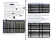
Voice Mail Administrator Features If your voice mail system has Automatic Speech Recognition (ASR) capability and it is enabled for the administrator mailbox, you can complete voice mail tasks by issuing spoken commands or by pressing dialpad digits. Accessing the Voice Mail Administrator’s Mailbox — Call the voice mail access number. — Say “Login” or press . — Say or enter the administrator mailbox number. Then enter the password, and press # .
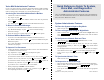
Default Administrator Feature Codes To Program System Speed-Dial Numbers: — While on-hook, enter 9 8 0 1 . — Enter the speed dial location code (000-999) or (0000-4999). — To change or program the name: Enter the desired name for the speed-dial number using one of the following methods: In numeric mode, the dialpad buttons are used to enter numbers 0-9, the # button is used for entering a hyphen, and the button is used for entering a colon.
Part Number 580.8001 INTER-TEL 5000 ADMINISTRATOR GUIDE Issue 2.
NOTICE This Inter-Tel 5000 Administrator Guide is released by Inter-Tel, Inc. as a guide for system and voice mail administrators. It provides information necessary to properly administer the system. ® The contents of this guide, which reflect current Inter-Tel standards, are subject to revision or change without notice. Some features or applications mentioned may require a future release and are not available in the initial release.
INTER-TEL® 5000 Contents ADMINISTRATOR GUIDE – Issue 2.3, September 2007 Contents FCC Regulations ix Safety Regulations xii Network Security Statement xiv Document Overview 1 Introduction . . . . . . . . . . . . . . . . . . . . . . . . . . . . . . . . . . . . . . . . . . . . . . . . . . . . . . . . . . . . . . 2 Endpoints and Phones . . . . . . . . . . . . . . . . . . . . . . . . . . . . . . . . . . . . . . . . . . . . . . . . . . . . . . 2 Changes to Issue 2.3. . . . . . . . . . . . . . . . . . .
Contents INTER-TEL® 5000 ADMINISTRATOR GUIDE – Issue 2.3, September 2007 Administrator Procedures 25 Introduction . . . . . . . . . . . . . . . . . . . . . . . . . . . . . . . . . . . . . . . . . . . . . . . . . . . . . . . . . . . . . 26 System Administrator Procedures . . . . . . . . . . . . . . . . . . . . . . . . . . . . . . . . . . . . . . . . . . . 27 Voice Mail Administrator Procedures . . . . . . . . . . . . . . . . . . . . . . . . . . . . . . . . . . . . . . . .
INTER-TEL® 5000 Contents ADMINISTRATOR GUIDE – Issue 2.3, September 2007 Call Screening . . . . . . . . . . . . . . . . . . . . . . . . . . . . . . . . . . . . . . . . . . . . . . . . . . . . . . . . . . 194 Reverse Transfer . . . . . . . . . . . . . . . . . . . . . . . . . . . . . . . . . . . . . . . . . . . . . . . . . . . . . . . . 194 Conference Calls . . . . . . . . . . . . . . . . . . . . . . . . . . . . . . . . . . . . . . . . . . . . . . . . . . . . . . . . 195 Record-A-Call . . . . . . . . . . .
Contents INTER-TEL® 5000 ADMINISTRATOR GUIDE – Issue 2.3, September 2007 Voice Processing Features 263 Introduction . . . . . . . . . . . . . . . . . . . . . . . . . . . . . . . . . . . . . . . . . . . . . . . . . . . . . . . . . . . . 265 Automated Attendant . . . . . . . . . . . . . . . . . . . . . . . . . . . . . . . . . . . . . . . . . . . . . . . . . . . . 265 Automatic Fax Detection. . . . . . . . . . . . . . . . . . . . . . . . . . . . . . . . . . . . . . . . . . . . . . . . . .
INTER-TEL® 5000 FCC Regulations ADMINISTRATOR GUIDE – Issue 2.3, September 2007 FCC Regulations IMPORTANT 1. This equipment complies with Part 68 of Federal Communications Commission (FCC) rules. On the side of the equipment Inter-Tel 5000 Base Server is a label that contains, among other information, the FCC registration number and ringer equivalence number (REN) for this equipment.
FCC Regulations INTER-TEL® 5000 ADMINISTRATOR GUIDE – Issue 2.3, September 2007 4. The telephone company may make changes in its facilities, equipment, operations, or procedures which may affect the operation of this equipment. If so, the customer shall be given advance notice so that any necessary modifications can be made in order to maintain uninterrupted service. 5.
INTER-TEL® 5000 FCC Regulations ADMINISTRATOR GUIDE – Issue 2.3, September 2007 NOTICE The telephone instruments specifically designed for this system have hearing aid-compatible handsets that are in compliance with section 68.316 of the FCC Rules. The IP SLA complies with UL60950/CSA60950 and EN 60950 standards and complies with EN 55022 and CFR 47 part 15 of the FCC Rules.
Safety Regulations INTER-TEL® 5000 ADMINISTRATOR GUIDE – Issue 2.3, September 2007 Safety Regulations IMPORTANT SAFETY INSTRUCTIONS NOTICE The “C US” indicator adjacent to the Canadian Standards Association (CSA) mark on the product label signifies that the Inter-Tel® 5000 Network Communications Solutions system has been evaluated to the applicable ANSI/UL and CSA Standards for use in both the United States and Canada. The CSA is a Nationally Recognized Testing Laboratory (NRTL).
INTER-TEL® 5000 Safety Regulations ADMINISTRATOR GUIDE – Issue 2.3, September 2007 11. Never push objects of any kind into this product through Inter-Tel 5000 Base Server slots as they may touch dangerous voltage points or short out parts that could result in a risk of fire or electric shock. Never spill liquid of any kind on the product. 12. To reduce the risk of electric shock, do not disassemble this product, but take it to a qualified serviceman when some service or repair work is required.
Network Security Statement INTER-TEL® 5000 ADMINISTRATOR GUIDE – Issue 2.
INTER-TEL® 5000 Document Overview ADMINISTRATOR GUIDE – Issue 2.3, September 2007 Document Overview Introduction . . . . . . . . . . . . . . . . . . . . . . . . . . . . . . . . . . . . . . . . . . . . . . . . . . . . . . . . . . . . . . 2 Endpoints and Phones . . . . . . . . . . . . . . . . . . . . . . . . . . . . . . . . . . . . . . . . . . . . . . . . . . . . . . 2 Changes to Issue 2.3. . . . . . . . . . . . . . . . . . . . . . . . . . . . . . . . . . . . . . . . . . . . . . . . . . . . . . . .
Document Overview INTER-TEL® 5000 ADMINISTRATOR GUIDE – Issue 2.3, September 2007 Introduction The Inter-Tel® 5000 Administrator Guide contains information that system administrators and voice mail administrators need to know about the Inter-Tel 5000 Network Communications Solutions family of products. The guide focuses on system hardware and software features and on the use of system administrator and voice mail administrator endpoint features needed to perform typical administrator tasks and activities.
INTER-TEL® 5000 Document Overview ADMINISTRATOR GUIDE – Issue 2.3, September 2007 Changes to Issue 2.3 Table 1 summarizes the features and Inter-Tel 5000 capabilities introduced in v2.3. Table 1. Inter-Tel 5000 v2.3 Feature and Capability Descriptions Feature or Capability Description Dual-port digital trunk module The Dual T1/E1/PRI Module (T1M-2) is the central hardware feature of v2.3.
Document Overview INTER-TEL® 5000 ADMINISTRATOR GUIDE – Issue 2.3, September 2007 Table 2. System Administrator Tasks and Procedure References (Continued) Task Procedure Reference Use diagnostic mode features to freeze and unfreeze database history on the local system. “Freezing/Unfreezing the System History” on page 61 Use diagnostic mode features to freeze and unfreeze database history on other systems in the network.
INTER-TEL® 5000 Document Overview ADMINISTRATOR GUIDE – Issue 2.3, September 2007 Chapters of the Administrator Guide This Administrator Guide includes the following chapters: • Document Overview: This chapter provides information about the document’s structure and content, associated documents, typographical methods used to call the reader’s attention to important information, and a listing of selected abbreviations and acronyms used throughout the document.
Document Overview INTER-TEL® 5000 ADMINISTRATOR GUIDE – Issue 2.3, September 2007 Multicultural English References This administrator guide supports the requirements of technicians in the United States of America (USA) and in the Inter-Tel Europe market, which includes the United Kingdom (UK). Because of this dual support, dual references are made to industry features, standards, and jargon, as appropriate throughout the document.
INTER-TEL® 5000 Document Overview ADMINISTRATOR GUIDE – Issue 2.3, September 2007 Hazard Identification and Supplemental Information This guide uses standardized graphic conventions to promote safe practices, to prevent or minimize damage to equipment, to avoid the corruption of data, and to clarify the Inter-Tel, Inc. position on certain technical or business issues.
INTER-TEL® 5000 Product Description ADMINISTRATOR GUIDE – Issue 2.3, September 2007 Product Description Introduction . . . . . . . . . . . . . . . . . . . . . . . . . . . . . . . . . . . . . . . . . . . . . . . . . . . . . . . . . . . . . 11 Technology Highlights . . . . . . . . . . . . . . . . . . . . . . . . . . . . . . . . . . . . . . . . . . . . . . . . . . . . . 11 System Configurations . . . . . . . . . . . . . . . . . . . . . . . . . . . . . . . . . . . . . . . . . . . . . . . . . . . .
Product Description INTER-TEL® 5000 ADMINISTRATOR GUIDE – Issue 2.3, September 2007 Basic Voice Mail . . . . . . . . . . . . . . . . . . . . . . . . . . . . . . . . . . . . . . . . . . . . . . . . . . . . . . . . . . 21 BVM Forward to E-Mail. . . . . . . . . . . . . . . . . . . . . . . . . . . . . . . . . . . . . . . . . . . . . . . . . . . 22 External Voice Processing Systems . . . . . . . . . . . . . . . . . . . . . . . . . . . . . . . . . . . . . . . . . . 22 Enterprise Messaging . . . . . . . . . . . .
INTER-TEL® 5000 Product Description ADMINISTRATOR GUIDE – Issue 2.3, September 2007 Introduction The Inter-Tel® 5000 platform provides an enhanced IP solution for small- and medium-sized business environments. Marketed as Inter-Tel CS-5200, CS-5400, and CS-5600 Communication Servers, each system supports IP endpoints, Inter-Tel digital endpoints, Inter-Tel IP softphones, standard single line and other endpoints.
Product Description INTER-TEL® 5000 ADMINISTRATOR GUIDE – Issue 2.3, September 2007 System Configurations The Inter-Tel 5000 platform can be configured as any of three IP-centric systems capable of private networking and IP, digital, and analog endpoint expansion. The Inter-Tel CS-5200, CS-5400, and CS-5600 systems are sold separately as self-contained, licensed kits.
INTER-TEL® 5000 Product Description ADMINISTRATOR GUIDE – Issue 2.3, September 2007 With v2.1 and later, the CS-5600 Processing Server (PS-1) also supports 16-port BVM and handles call processing chores for the entire system. It controls and communicates with the Base Server across the customer’s LAN. For more details about BVM, see “Basic Voice Mail” on page 287.
Product Description INTER-TEL® 5000 ADMINISTRATOR GUIDE – Issue 2.3, September 2007 Networking and System Features The Inter-Tel 5000 platform supports the following networking and system-wide features: • Networking over IP. • Networking over T1 and E1 spans. • Can synchronize network time with an atomic clock. • Wide Area Network (WAN) Fail Survivability.
INTER-TEL® 5000 Product Description ADMINISTRATOR GUIDE – Issue 2.3, September 2007 Digital Capability The addition of one or two Digital Equipment Interface (DEI) units to the Inter-Tel 5000 Base Server adds digital capability to the Inter-Tel 5000 platform and provides the same call processing functionality available to IP endpoints.
Product Description INTER-TEL® 5000 ADMINISTRATOR GUIDE – Issue 2.3, September 2007 Trunks and Endpoints The Inter-Tel 5000 platform supports the following trunks, spans, gateways, and endpoints: • Central Office (CO) [Local Exchange] Trunks: Up to 12 loop start [local exchange] trunks can be installed in increments of four trunks per LSM-4 module. In addition, two loop start trunks can be installed in the RJ-14 port built in on the Inter-Tel 5000 Base Server.
INTER-TEL® 5000 Product Description ADMINISTRATOR GUIDE – Issue 2.3, September 2007 • Mini-DSS: The Inter-Tel 5000 platform supports a Mini-DSS Unit that provides onebutton access to 16 extension numbers and/or feature buttons/resources. • Direct Station Select (DSS)/Busy Lamp Field (BLF): The Inter-Tel 5000 platform supports two 60-button DSS/BLF Units and one 50-button model. Installation requires DEI and DEM-16 equipment and data port modules. See “Digital Capability” on page 15.
Product Description INTER-TEL® 5000 ADMINISTRATOR GUIDE – Issue 2.3, September 2007 USB Security Key for the PS-1 Unit The Inter-Tel CS-5600 system requires that a USB security key reside in the PS-1 unit. However, the Base Server does not need a USB security key. The administrator must upload the appropriate software license to the PS-1. System Alarms for Insufficient Licensing Attempts to activate an unlicensed DEI unit will trigger Alarm 130 and the unit will not come online.
INTER-TEL® 5000 Product Description ADMINISTRATOR GUIDE – Issue 2.3, September 2007 Voice Processing System Application Options Inter-Tel voice processing systems support several voice processing system applications. Depending on your site’s voice processing system, equipment, and licensing, you may have access to one or more of the following voice processing system features. Automated Attendant Automated Attendant is a programmable feature that provides automated call answering services.
Product Description INTER-TEL® 5000 ADMINISTRATOR GUIDE – Issue 2.3, September 2007 Call Routing Announcement The Call Routing Announcement (CRA) application can be used in place of a playback device and is useful for programming Hunt Group announcement and overflow stations. When called, the CRA application plays a recording and then hangs up. The CRA application uses digit translation to help calling parties reach their intended destinations.
INTER-TEL® 5000 Product Description ADMINISTRATOR GUIDE – Issue 2.3, September 2007 Scheduled Time-based Application Routing Scheduled Time-based Application Routing (STAR) enhances the programmability of the voice mail application greetings. Applications can be programmed to play alternative greetings for holidays and weekends. A STAR application is a table of up to 20 entries that serves as a “routing table.” STAR tells the voice processing system which application to use to respond to incoming calls.
Product Description INTER-TEL® 5000 ADMINISTRATOR GUIDE – Issue 2.3, September 2007 BVM Forward to E-Mail This feature enables BVM to forward voice mail messages as a .wav file attachments to e-mail messages. Features provide the following benefits: • Allows each mailbox to be configured with a different E-Mail address. • Operates with an industry standard SMTP mail server. • Each mailbox can be designated to store, forward, or store-and-forward messages.
INTER-TEL® 5000 Product Description ADMINISTRATOR GUIDE – Issue 2.3, September 2007 Voice Mail Networking A voice processing system can be installed on any or all nodes in the user’s network. These voice processing systems can also be networked together to allow a caller to leave a message on the local voice processing system for a mailbox located on another voice processing system in the network. Maximum capacities of networked voice processing systems are listed in Table 4. Table 4.
INTER-TEL® 5000 Administrator Procedures ADMINISTRATOR GUIDE – Issue 2.3, September 2007 Administrator Procedures Introduction . . . . . . . . . . . . . . . . . . . . . . . . . . . . . . . . . . . . . . . . . . . . . . . . . . . . . . . . . . . . . 26 System Administrator Endpoint Designation . . . . . . . . . . . . . . . . . . . . . . . . . . . . . . . . . 26 Scheduled Delayed Major Resets . . . . . . . . . . . . . . . . . . . . . . . . . . . . . . . . . . . . . . . . . .
Administrator Procedures INTER-TEL® 5000 ADMINISTRATOR GUIDE – Issue 2.3, September 2007 Introduction When programming your site’s database, the Inter-Tel-certified technician can program an endpoint’s extension as both a system administrator and a voice mail administrator. Sometimes the two jobs are handled by the same person. You can use an endpoint that has been designated as an administrator endpoint to perform certain programming tasks for the call processing system and/or the voice mail system.
INTER-TEL® 5000 Administrator Procedures ADMINISTRATOR GUIDE – Issue 2.
Administrator Procedures INTER-TEL® 5000 ADMINISTRATOR GUIDE – Issue 2.3, September 2007 Setting System Date and Time IMPORTANT The Inter-Tel 5000 Platform supports the Automatic Daylight Saving Time (British Summer Time, in Europe) feature. However, the Enable Daylight Saving Time flag in DB Programming must be set to Yes to use the Automatic Daylight Saving Time/British Summer Time feature.
INTER-TEL® 5000 Administrator Procedures ADMINISTRATOR GUIDE – Issue 2.3, September 2007 Setting Network Date and Time Occasionally, the network time or date needs to be reset, such as when the system is defaulted or when daylight-saving time/British summer time is implemented. Any system administrator can change the date and time that appears on all display endpoints and that appears in the SMDR reports in the network.
Administrator Procedures INTER-TEL® 5000 ADMINISTRATOR GUIDE – Issue 2.3, September 2007 Synchronizing Network Time System administrators can synchronize the minutes past the hour across the network without changing the hour. This is useful when the nodes are in different time zones. If the node time is off by more than 30 minutes, synchronizing the minutes may cause the hour to change.
INTER-TEL® 5000 Administrator Procedures ADMINISTRATOR GUIDE – Issue 2.3, September 2007 Depending on the database changes made, the system may require a reset after programming. If so, the system will prompt you for a reset and ask if it should be done immediately or delayed. Delaying the reset may prevent interruption in service. However, if a reset is required it should be done as soon as possible to permit proper system operation. NOTICE Possible interruption of calls in progress.
Administrator Procedures INTER-TEL® 5000 ADMINISTRATOR GUIDE – Issue 2.3, September 2007 Station Programming You can use your administrator endpoint to program the following endpoint information: • Create or delete administrator endpoints: You can program any non-single line InterTel endpoint as an additional administrator endpoint, or you can delete the designation of an endpoint as an administrator endpoint.
INTER-TEL® 5000 5. Administrator Procedures ADMINISTRATOR GUIDE – Issue 2.3, September 2007 The display shows ENTER ENDPOINT OPTION. Select one of the following: • Endpoint Flags: This option allows you to set the administrator endpoint, attendant, and House Phone flags. To select it, press 1 or the ENDPOINT FLAGS menu button. Three flags can be programmed: Administrator, Attendant, and House Phone. However, you cannot program the Administrator flag for your own endpoint or for a single line endpoint.
Administrator Procedures INTER-TEL® 5000 ADMINISTRATOR GUIDE – Issue 2.3, September 2007 The default COS numbers for the U.S. are provided in Table 6 and the default COS numbers for Europe are provided in Table 7. Table 6. Default Class of Service (COS) Numbers for the U.S. COS 02 – Deny Area/Office COS 06 – Deny Equal Access COS 03 – Deny Operator COS 07 – Deny Local Calls COS 04 – Deny Toll Access COS 08 – Denied Numbers COS 05 – Deny International COS 09 – Allowed Numbers Table 7.
INTER-TEL® 5000 Administrator Procedures ADMINISTRATOR GUIDE – Issue 2.3, September 2007 Figure 1.
Administrator Procedures INTER-TEL® 5000 ADMINISTRATOR GUIDE – Issue 2.3, September 2007 System Programming You can use your administrator endpoint to program the following system-wide information: • Define Do-Not-Disturb (DND) messages: The messages for the Do-Not-Disturb feature can be reprogrammed through an administrator endpoint. Administrators can delete or change messages 01–20 to any value up to 16 characters. For feature description and DND message details, see “Do-Not-Disturb” on page 238.
INTER-TEL® 5000 Administrator Procedures ADMINISTRATOR GUIDE – Issue 2.3, September 2007 • Program new extension numbers for endpoints: The extension number for any endpoint can be changed by an Administrator. The new extension number cannot conflict with an existing number. • Swap extensions: An extension number can be relocated (swapped) to another endpoint.
Administrator Procedures INTER-TEL® 5000 ADMINISTRATOR GUIDE – Issue 2.3, September 2007 • • Page 38 Password: This option allows you to set a password that limits access to the Administrator programming feature. To select it, press 2 or the PASSWORD menu button. Then do the following: – The display shows CHANGE PASSWORD TO. Enter a password of up to eight digits, then press # . To erase the password and leave it blank, just press # . – The display shows VERIFY PASSWORD.
INTER-TEL® 5000 • Administrator Procedures ADMINISTRATOR GUIDE – Issue 2.3, September 2007 Station Extensions: This option allows you to assign new extension numbers to stations/endpoints/phones. To select it, press 4 or the STN EXTENSION menu button. If programming an endpoint: – 1 or CHANGE EXT. The display shows ENTER ENDPOINT EXTENSION. Enter the extension number of the endpoint to be programmed using Press one of the following methods.
Administrator Procedures INTER-TEL® 5000 ADMINISTRATOR GUIDE – Issue 2.3, September 2007 If swapping endpoints: • Press 2 or SWAP EXTS. The display shows ENTER ENDPOINT EXTENSION. Enter the first extension number to be swapped using one of the following methods. (If you enter an invalid extension number, you hear reorder tones and must try again.) Enter a complete number: Enter the extension number using your dialpad. When a valid number is entered, the circuit information is displayed.
INTER-TEL® 5000 Administrator Procedures ADMINISTRATOR GUIDE – Issue 2.3, September 2007 Figure 2.
Administrator Procedures INTER-TEL® 5000 ADMINISTRATOR GUIDE – Issue 2.3, September 2007 Trunk Programming The trunk information that can be programmed by an administrator endpoint includes the following: Individual trunks: • Answer Supervision type: Answer Supervision determines whether the system should consider a call valid when it receives polarity reversal from the central office or wait for the Valid Call timer to expire.
INTER-TEL® 5000 Administrator Procedures ADMINISTRATOR GUIDE – Issue 2.3, September 2007 Trunk groups: • Day/Night Answer Access: You can program separate lists for endpoints with allowedanswer access in day and night modes. • Day/Night Ring-In: You can program separate lists of endpoints with ring-in for day and night modes. • Change Toll Restrictions: You can program toll restriction classes of service for the trunk groups. Classes of service are described in detail on page 143.
Administrator Procedures INTER-TEL® 5000 ADMINISTRATOR GUIDE – Issue 2.3, September 2007 4. To Program an Individual Trunk: Press Then program trunk options as follows: 1 or the INDIVIDUAL TRUNK menu button. • The display shows ENTER TRUNK EXTENSION. Enter the extension number of the trunk to be programmed using one of the methods described on page 43. • The display shows INDIVIDUAL TRUNK OPTION. Enter one of the following options.
INTER-TEL® 5000 5. Administrator Procedures ADMINISTRATOR GUIDE – Issue 2.3, September 2007 To Program A Trunk Group: Press program the trunk group, as follows: 2 or the TRUNK GROUP menu button. Then • The display shows ENTER TRUNK GRP EXTENSION. Enter the extension number of the trunk group to be programmed using one of the methods described on page 43. • The display shows ENTER TRUNK GROUP OPTION. Select one of the following options.
Administrator Procedures INTER-TEL® 5000 ADMINISTRATOR GUIDE – Issue 2.3, September 2007 For U.S.
INTER-TEL® 5000 Administrator Procedures ADMINISTRATOR GUIDE – Issue 2.3, September 2007 6. When finished with all programming, press # while the ENTER DATABASE OPTION prompt is displayed. This ends the programming session. 7. If a system reset is required, the display shows ENTER SYS RESET OPTION. Do one of the following: • Delayed Reset: Press 1 or the DELAYED menu button to delay the reset. The display shows DELAYED RESET SCHEDULED. The system will be reset at the preprogrammed time.
Administrator Procedures INTER-TEL® 5000 ADMINISTRATOR GUIDE – Issue 2.3, September 2007 Figure 3.
INTER-TEL® 5000 Administrator Procedures ADMINISTRATOR GUIDE – Issue 2.3, September 2007 Figure 3.
Administrator Procedures INTER-TEL® 5000 ADMINISTRATOR GUIDE – Issue 2.3, September 2007 Programming System Speed Dial System Speed Dial numbers and names can be programmed by the installer or at any administrator endpoint. Speed Dial Numbers System Speed Dial numbers can contain up to 48 digits each and can include hookflashes and/ or pauses for dialing a series of numbers. For example, the Speed Dial number can contain an SCC local number, a pause, an access code, and the phone number.
INTER-TEL® 5000 Administrator Procedures ADMINISTRATOR GUIDE – Issue 2.3, September 2007 Table 9 shows the dialpad equivalents for English/Spanish and for Japanese language characters. Japanese characters are included in your standard software license and can be programmed as the Primary or Secondary Language. Table 9.
Administrator Procedures INTER-TEL® 5000 ADMINISTRATOR GUIDE – Issue 2.3, September 2007 4. When the display shows ENTER NUMBER, enter the number, up to 48 digits, to be stored using the dialpad, one of the Speed Dial buttons, or the REDIAL button. If necessary, use the MUTE button to back up and erase existing numbers. (Display endpoints show the number as it is entered.
INTER-TEL® 5000 Administrator Procedures ADMINISTRATOR GUIDE – Issue 2.3, September 2007 In DB Programming, Mini-DSS and DSS/BLF buttons may also be programmed for direct access to other resources such as paging zones, or they can be assigned feature codes. See “Endpoint Feature Codes” on page 316. Busy lamp indication is provided to show the idle or busy status of the resource or feature. Programming a DSS button as a resource does not always provide a transfer capability.
Administrator Procedures INTER-TEL® 5000 ADMINISTRATOR GUIDE – Issue 2.3, September 2007 2. If necessary, wait for an answer and announce the call. If you are calling a device that does not accept handsfree calls (such as Automated Attendant location), the display shows HANG UP TO FINISH TRANSFER. 3. You have the following options: To complete the transfer: Hang up or press another Call button. The display shows CALL TRANSFERRED TO .
INTER-TEL® 5000 Administrator Procedures ADMINISTRATOR GUIDE – Issue 2.3, September 2007 On remote nodes, network-wide alarms will indicate the name of the node on which the alarm occurred. The node name is obtained from the username. To respond to a minor alarm from any alarm display endpoint: 1. When a minor alarm indication appears, write down the alarm information. 2. While on-hook, clear the alarm by entering the Clear System Alarm feature code, 9850, or the Clear Network Alarm feature code, 9851.
Administrator Procedures INTER-TEL® 5000 ADMINISTRATOR GUIDE – Issue 2.3, September 2007 To use menu buttons to clear alarms, do one of the following: • Press CLEAR ALARM to clear the currently displayed alarm. The display shows SYSTEM (or NETWORK) ALARM CLEARED, and the next highest priority alarm is displayed. If there are no more alarms, the display shows the idle menu. or • Press CLEAR ALL ALARMS to clear all alarms.
INTER-TEL® 5000 Administrator Procedures ADMINISTRATOR GUIDE – Issue 2.3, September 2007 The queue holds up to 30 alarms, with priority, 1 (critical) to 4 (low), as shown in the following lists.
Administrator Procedures INTER-TEL® 5000 ADMINISTRATOR GUIDE – Issue 2.3, September 2007 Networked Inter-Tel 5000 and Axxess systems containing nodes running Inter-Tel Axxess v8.1 or earlier require special attention because those nodes do not have the Alarm Queue feature. In networks that include these early-version Axxess systems, a broadcast message is sent only when the most recent network alarm is cleared. When the message is sent, that network alarm is cleared on all nodes in the system.
INTER-TEL® 5000 Administrator Procedures ADMINISTRATOR GUIDE – Issue 2.3, September 2007 Resetting the Internal Modem The internal modem must be reset if it fails to answer an incoming call or is out of sync with an external modem. NOTICE Possible data corruption. Do not reset the modem if it is connected to a DB Programming session. If you do, the programming session is dropped, potentially corrupting the database.
Administrator Procedures INTER-TEL® 5000 ADMINISTRATOR GUIDE – Issue 2.3, September 2007 Seizing a Device For troubleshooting purposes, the Seize Device feature code allows an administrator to enable diagnostics mode and then seize a specific trunk or extension by entering the module, circuit, and device number. The Seize Device is affected by trunk restriction. The administrator endpoint must have outgoing access permission for the trunk to seize it.
INTER-TEL® 5000 Administrator Procedures ADMINISTRATOR GUIDE – Issue 2.3, September 2007 Freezing/Unfreezing the System History When certain system failures occur, service personnel might request a “system history freeze.” This allows them access to the system database so that they can analyze system activity for the time period preceding the alarm. To freeze or unfreeze system history: IMPORTANT Do not perform this procedure unless directed to do so by service personnel. 1.
Administrator Procedures INTER-TEL® 5000 ADMINISTRATOR GUIDE – Issue 2.3, September 2007 Voice Mail Administrator Procedures If your endpoint has been programmed as the voice mail administrator, you can use special features that are not provided to other voice mailbox owners.
INTER-TEL® 5000 Administrator Procedures ADMINISTRATOR GUIDE – Issue 2.3, September 2007 To access the voice mail administrator’s mailbox and menu: 1. Dial the voice mail access number. 2. Say “Login” or press 3. Say or enter the voice mail administrator’s mailbox number. 4. Enter the password and then press 5. Say “Nine” or press for entering the 9 . to identify yourself as a subscriber. 9 # . to reach the voice mail administrator menu.
Administrator Procedures INTER-TEL® 5000 ADMINISTRATOR GUIDE – Issue 2.3, September 2007 Mailbox and Extension ID Personal Options Voice Mail mailboxes provide personal options that allow the user to customize messaging functions. However, before personal mailbox options can be changed, the mailbox must be initialized by the user. For programming instructions to change personal options, refer to the applicable Inter-Tel Endpoint User Guide, which are listed under “Endpoint User Guides” on page 358.
INTER-TEL® 5000 Administrator Procedures ADMINISTRATOR GUIDE – Issue 2.3, September 2007 • Message Search Order: This option allows the user to determine how to retrieve saved or new messages based on the date and time they were received. The message search order can be the earliest-received messages first (First In/First Out), or the latestreceived messages first (Last In/First Out).
Administrator Procedures INTER-TEL® 5000 ADMINISTRATOR GUIDE – Issue 2.3, September 2007 To change the recorded directory name for a mailbox: 1. Access the voice mail administrator’s mailbox and menu. See page 63. 2. Say “Mailbox Maintenance” or press option. 3. Say or enter the mailbox or extension ID to be accessed. You hear the Personal Options Menu. 4. Say “Name” or press 5. 2 2 to access the Mailbox/Group List Maintenance . The recorded name is played.
INTER-TEL® 5000 6. You can then do any of the following: • Say “Time/Date” or press • Say “Source” or press • For voice mail, say “Length” or press option. • For e-mail, say “Subject” or press 3 • For faxes, say “Pages” or press 3 to enable or disable the pages option. • Say “All Options” or press Options Menu. to enable all options and return to the Personal • Say “None” or press Options Menu. NOTE 7. Administrator Procedures ADMINISTRATOR GUIDE – Issue 2.
Administrator Procedures INTER-TEL® 5000 ADMINISTRATOR GUIDE – Issue 2.3, September 2007 6. 7. 8. 9. Say “Time” or press 2 . Then say or enter the time you want the message notification to start and stop. Enter or say the times with two digits for the hour and two digits for the minutes (e.g., 0900 = 9:00). If entering the time in 12-hour format: • Say “AM” or press • Say “PM” or press 2 for p.m. For 24-hour notification, set the starting and ending times to be the same.
Administrator Procedures ADMINISTRATOR GUIDE – Issue 2.3, September 2007 INTER-TEL® 5000 To change a fax destination number: 1. Access the voice mail administrator’s mailbox and menu. See page 63. 2. Say “Mailbox Maintenance” or press option. 3. Say or enter the mailbox or extension ID to be accessed. You hear the Personal Options menu. 4. Say “More” or press 5. Say “Number” or press 6. Say or enter the number of the fax destination. 7.
Administrator Procedures INTER-TEL® 5000 ADMINISTRATOR GUIDE – Issue 2.3, September 2007 Changing a Group List Name A Group List is a collection of mailboxes that is programmed in DB Programming. Subscribers can use Group Lists to send messages to several mailboxes simultaneously. With the voice mail administrator mailbox, you can record a name for the Group Lists that have been programmed in the system.
INTER-TEL® 5000 4. Administrator Procedures ADMINISTRATOR GUIDE – Issue 2.3, September 2007 When prompted, say or enter the fax document number. One of the following occurs when you enter the number: If the document number does not already exist, the system asks you to verify the number. Say “Yes” or press # if the number is correct and go to the next step. Or, say “Reenter” or press 3 if you want to re-renter the number. If the document number already exists, the system asks if you want to replace it.
Administrator Procedures INTER-TEL® 5000 ADMINISTRATOR GUIDE – Issue 2.3, September 2007 In DB Programming, link several greetings together for one application and/or use the special UCD/ACD hunt group characters that tell the caller how many calls are ahead and how long the wait will be. If you use the voice mail administrator’s mailbox to record or assign a recording to an application with a list of several recordings, your input will change only the first entry in the list.
Administrator Procedures ADMINISTRATOR GUIDE – Issue 2.3, September 2007 INTER-TEL® 5000 9. When finished, select one of the following options: • Say “Replay” or press • Say “Append” or press 2 • Say “Erase” or press to erase and re-record the message. • Say “Accept” or press to replay the message. 1 3 # to add to the message. to accept. To assign custom audiotex recordings to specific application extension numbers: 1. Access the voice mail administrator’s mailbox and menu. See page 63.
Administrator Procedures INTER-TEL® 5000 ADMINISTRATOR GUIDE – Issue 2.3, September 2007 A list of all U.S. English prerecorded prompts is provided, beginning on page 345. IMPORTANT If you change the text of the prompts, keep the content similar to the default text. Otherwise, the prompts will not make sense to the listeners when played by voice mail. You must record custom recordings using the voice mail administrator endpoint handset. EM v1.0 does not support importing .
INTER-TEL® 5000 Hardware and Endpoints ADMINISTRATOR GUIDE – Issue 2.3, September 2007 Hardware and Endpoints Introduction . . . . . . . . . . . . . . . . . . . . . . . . . . . . . . . . . . . . . . . . . . . . . . . . . . . . . . . . . . . . . 76 Base Server IP and SIP Emergency Calls From a Remote Site . . . . . . . . . . . . . . . . . . . 76 IP Endpoints. . . . . . . . . . . . . . . . . . . . . . . . . . . . . . . . . . . . . . . . . . . . . . . . . . . . . . . . . . . . .
Hardware and Endpoints INTER-TEL® 5000 ADMINISTRATOR GUIDE – Issue 2.3, September 2007 Introduction The Inter-Tel 5000 platform can be licensed and programmed to support multi-protocol, IP, SIP, digital, and single line endpoints, softphone applications, as well as other endpoints and performance-enhancing hardware.
INTER-TEL® 5000 Hardware and Endpoints ADMINISTRATOR GUIDE – Issue 2.3, September 2007 Also, if power to an Inter-Tel 5000 system fails, IP and SIP endpoints will not operate at remote sites or at the main system location without appropriate gateway equipment and programming, as described above. All IP and SIP endpoint users should be alerted to this potentially hazardous situation.
Hardware and Endpoints INTER-TEL® 5000 ADMINISTRATOR GUIDE – Issue 2.3, September 2007 Table 12.
INTER-TEL® 5000 Hardware and Endpoints ADMINISTRATOR GUIDE – Issue 2.3, September 2007 Table 12.
Hardware and Endpoints INTER-TEL® 5000 ADMINISTRATOR GUIDE – Issue 2.3, September 2007 ITP and SIP Feature Exceptions Some endpoints cannot fully support certain features due to hardware or software restrictions. These exceptions are listed below by endpoint type. Model 8600: The Model 8600 endpoint operates in ITP or SIP mode.
Hardware and Endpoints ADMINISTRATOR GUIDE – Issue 2.3, September 2007 INTER-TEL® 5000 Feature Codes: The two feature codes in Table 13 function differently, depending on the mode the endpoint is operating in. Table 13. Feature Codes with Different Meanings for ITP and SIP Modes Feature Name Feature Code ITP Mode SIP Mode 300 Displays the system date and time, username, and extension. Displays the IP address of the endpoint.
Hardware and Endpoints INTER-TEL® 5000 ADMINISTRATOR GUIDE – Issue 2.3, September 2007 Table 14. Flashing Light Indicators for IP and Multi-Protocol Endpoints (Continued) Button Steady 0 IPM DND Endpoint is in Do-NotDisturb. FEATURE2 The feature is in use. FWD Calls are being forwarded. HUNT GROUP Slow 30 IPM All stations in hunt group are unavailable. IC MSG Endpoint is in alphanumeric mode. MUTE Microphone is muted. SPEAKER Speakerphone is on or ready for use.
INTER-TEL® 5000 Hardware and Endpoints ADMINISTRATOR GUIDE – Issue 2.3, September 2007 Table 14. Flashing Light Indicators for IP and Multi-Protocol Endpoints (Continued) Button Steady 0 IPM TRUNK Trunk is in use at another endpoint, in a conference at your endpoint, or it is unplugged. Slow 30 IPM Trunk is in use at your endpoint. Medium 120 IPM Fast 240 IPM Trunk is recalling from hold or transfer. Trunk is ringing in, camped on (waiting), or in busy trunk callback queue to your endpoint.
Hardware and Endpoints INTER-TEL® 5000 ADMINISTRATOR GUIDE – Issue 2.3, September 2007 IP and SIP Endpoint Ports and Connectors The ports and connectors on IP and SIP endpoints vary depending on the model number. The following ports and connectors may be included on your endpoint: Page 84 • Headset Jack: Connects to a headset. • Handset Jack: Connects to a handset. • Combined Headset/ Handset Jack: Connects to a headset or handset.
INTER-TEL® 5000 Hardware and Endpoints ADMINISTRATOR GUIDE – Issue 2.3, September 2007 Battery Packs and Chargers Models 8664 and 8665 require a charged battery pack to operate. The Nickel Metal Hydride (NiMH) rechargeable battery pack needs to be charged periodically. A charged battery pack provides four hours of talk time or 80 hours of idle time. To save battery power, instruct the user to place the endpoint in idle mode at the end of every call.
Hardware and Endpoints INTER-TEL® 5000 ADMINISTRATOR GUIDE – Issue 2.3, September 2007 Because IP endpoints connected on P2P calls do not use Inter-Tel 5000 resources, users cannot access Agent Help, Record-A-Call, and Station Monitor features. NOTICE Passing real-time streaming data, such as audio, through encrypted virtual private networks (VPN) may significantly impact the network performance, router and firewall functionality, and audio quality.
INTER-TEL® 5000 Hardware and Endpoints ADMINISTRATOR GUIDE – Issue 2.3, September 2007 Features Common to IP and Digital Inter-Tel Endpoints Although their basic technologies and network connecting methods differ, IP and digital InterTel endpoints share both some physical characteristics and software features. For example, both types of endpoint possess similar LCD windows, Call buttons, and feature buttons.
Hardware and Endpoints INTER-TEL® 5000 ADMINISTRATOR GUIDE – Issue 2.3, September 2007 Display Endpoint Screens Several IP, SIP, and digital endpoint models are equipped with liquid crystal display (LCD) screens that show caller and feature information. NOTE For endpoints operating in SIP mode, voice mail displays are not supported, but the user does receive audio prompts.
INTER-TEL® 5000 Hardware and Endpoints ADMINISTRATOR GUIDE – Issue 2.3, September 2007 Enabling the Alternate IP/Digital Endpoint Menu flag allows Centrex features to be accessed more easily, using the FLASH menu option. Figure 4. Model 8560, 8660, or 8662 LCD Screen LCD with six 16-character lines Menu selection buttons Menu selection buttons Figure 5.
Hardware and Endpoints INTER-TEL® 5000 ADMINISTRATOR GUIDE – Issue 2.3, September 2007 LCD Contrast Adjustment The contrast of the LCD screens on IP and digital display endpoints is adjustable. Eight different contrast levels are available. Examples follow for a two-line endpoint and a six-line endpoint. For instructions to adjust the contrast on a specific endpoint, refer to the User Guide, as identified in “Endpoint User Guides” on page 358.
INTER-TEL® 5000 Hardware and Endpoints ADMINISTRATOR GUIDE – Issue 2.3, September 2007 Default Inter-Tel Endpoint Feature Buttons When the system is in the default state, all endpoints are in the same keymap group and have the following feature buttons. Feature code descriptions start on page 113. The Special button is signified with the infinity symbol ( ∞ ). Table 15 summarizes the functions of endpoint feature buttons. Table 15.
Hardware and Endpoints INTER-TEL® 5000 ADMINISTRATOR GUIDE – Issue 2.3, September 2007 Keymaps A keymap group determines the layout of the buttons for all the endpoints assigned to that group. If any of the buttons in the keymap group are user-programmable or undefined, they can be changed by the endpoint user. Up to 250 different keymap groups can exist. Each node contains its own keymap programming. Each Inter-Tel endpoint is assigned a standard keymap and can also have an alternate keymap.
INTER-TEL® 5000 Keymaps Hardware and Endpoints ADMINISTRATOR GUIDE – Issue 2.3, September 2007 • Feature Button: Programmed with feature codes. The feature code appears in the same button location on all endpoints assigned to the keymap and cannot be changed by the endpoint user. • Forward Button: Can be programmed with any of the Call Forwarding feature codes. The forwarding code used by the button can be changed by the endpoint user.
Hardware and Endpoints INTER-TEL® 5000 ADMINISTRATOR GUIDE – Issue 2.3, September 2007 • Undefined Button: Any button can be left undefined if it will not be needed. It can be programmed, like a user-programmable button, as described above. If the endpoint user or programmer returns the endpoint to default values, the button will return to being “undefined.” • Up Button: Not required for digital endpoints.
INTER-TEL® 5000 Hardware and Endpoints ADMINISTRATOR GUIDE – Issue 2.3, September 2007 Any Inter-Tel endpoint button can be designated as a secondary extension button, but buttons with lamps are recommended so that the secondary extension button can show call status. Table 17 on page 100 shows the definition for each possible lamp flash rate. The secondary extension button shows only calls that appear under the Call buttons at the primary endpoint.
Hardware and Endpoints INTER-TEL® 5000 ADMINISTRATOR GUIDE – Issue 2.3, September 2007 Headsets An electret headset can be connected to Inter-Tel Model 8600, 8620, and 8660 IP endpoints or to Inter-Tel Model 8500, 8520, and 8560 digital endpoints. Pressing the Speaker button connects or disconnects calls when the headset is attached. Some headsets are equipped with a power-saver mode that disables the headset after a period of silence.
INTER-TEL® 5000 Hardware and Endpoints ADMINISTRATOR GUIDE – Issue 2.3, September 2007 Disconnecting a Headset The following procedures describe how to disconnect a headset from an Inter-Tel endpoint. To disconnect the headset from a Model 8620 or 8660 IP or a Model 8520 or 8560 digital endpoint: 1. Unplug the headset cord from the back of the endpoint. 2. While on-hook, enter the Headset Off feature code (316) or the Headset On/Off feature code (317). The display shows HEADSET MODE OFF.
Hardware and Endpoints INTER-TEL® 5000 ADMINISTRATOR GUIDE – Issue 2.3, September 2007 Inter-Tel Digital Endpoints The following paragraphs describe the features supported by Inter-Tel endpoints. Throughout this guide, the term “Inter-Tel endpoint” refers to full-feature endpoints manufactured and sold by Inter-Tel. The term does not apply to industry-standard single line DTMF endpoints.
INTER-TEL® 5000 Hardware and Endpoints ADMINISTRATOR GUIDE – Issue 2.3, September 2007 Executive and Professional Display Speakerphones Each Executive and Professional Display endpoint has a built-in, integrated speakerphone that allows on-hook dialing and handsfree operation on outside calls and inside (intercom) calls.
Hardware and Endpoints INTER-TEL® 5000 ADMINISTRATOR GUIDE – Issue 2.3, September 2007 A digital endpoint user can set up a conference and then, once it is established, press the ∞ (Special button) and Speaker (or press ∞ and enter the Enhanced Speakerphone feature code, 310) to have an enhanced speakerphone call in the conference. Digital Endpoint Flashing Light Indicators Table 17 summarizes digital endpoint LED flash rates in interruptions per minute (IPM). Table 17.
INTER-TEL® 5000 Hardware and Endpoints ADMINISTRATOR GUIDE – Issue 2.3, September 2007 Table 17. Inter-Tel Digital Endpoint LED Flash Rates (Continued) Steady 0 IPM SPEED DIAL or Mini-DSS TRUNK Slow 30 IPM Station is busy or unplugged. (Red LED) Station is in Do-Not-Disturb. (Red LED) Trunk is in use at another station, in a conference at your station, or is unplugged. (Red LED) Trunk is in use at your station. (Green LED*) Medium 120 IPM Trunk is recalling from hold or transfer.
Hardware and Endpoints INTER-TEL® 5000 ADMINISTRATOR GUIDE – Issue 2.3, September 2007 Digital Endpoint Data Port Modules As described in the following paragraphs, two types of Data Port Modules that can be connected to Inter-Tel digital Models 8520 and 8560, Executive Display, Professional Display, Standard Display, and Associate Display endpoints.
INTER-TEL® 5000 Hardware and Endpoints ADMINISTRATOR GUIDE – Issue 2.3, September 2007 Off Premises Extensions (OPX) Off premises extensions are remote single line DTMF endpoints connected to the Inter-Tel system through telephone company OPX circuits, or customer-provided circuits. OPX endpoint users gain access to the features by hookflashing [recalling] (pressing and releasing the hookswitch quickly) and entering feature codes.
Hardware and Endpoints INTER-TEL® 5000 ADMINISTRATOR GUIDE – Issue 2.3, September 2007 Optional System Equipment The following optional equipment can be purchased and installed with the Inter-Tel system: Voice Processing: Depending on the selected voice processing option, provides multiport integrated voice processing features (e.g., Voice Mail, Automated Attendant, Hunt Group announcement and overflow, SMDR storage, Record-A-Call, etc.) Inter-Tel supports three types of voice processing systems.
INTER-TEL® 5000 System Features ADMINISTRATOR GUIDE – Issue 2.3, September 2007 System Features Introduction . . . . . . . . . . . . . . . . . . . . . . . . . . . . . . . . . . . . . . . . . . . . . . . . . . . . . . . . . . . . 109 Types of Software Features . . . . . . . . . . . . . . . . . . . . . . . . . . . . . . . . . . . . . . . . . . . . . . . . 109 Standard Features . . . . . . . . . . . . . . . . . . . . . . . . . . . . . . . . . . . . . . . . . . . . . . . . . . . . . 109 Premium Features. . .
System Features INTER-TEL® 5000 ADMINISTRATOR GUIDE – Issue 2.3, September 2007 Volume Controls . . . . . . . . . . . . . . . . . . . . . . . . . . . . . . . . . . . . . . . . . . . . . . . . . . . . . . 151 Selectable Ring Tone . . . . . . . . . . . . . . . . . . . . . . . . . . . . . . . . . . . . . . . . . . . . . . . . . . 153 Default Endpoint Identification on Display . . . . . . . . . . . . . . . . . . . . . . . . . . . . . . . . . 153 “All Transient Displays” Endpoint Flag. . . . . . . . . . . . . .
INTER-TEL® 5000 System Features ADMINISTRATOR GUIDE – Issue 2.3, September 2007 Call Transfer . . . . . . . . . . . . . . . . . . . . . . . . . . . . . . . . . . . . . . . . . . . . . . . . . . . . . . . . . . . 191 Feature Codes . . . . . . . . . . . . . . . . . . . . . . . . . . . . . . . . . . . . . . . . . . . . . . . . . . . . . . . . 191 Transferring Conference Calls . . . . . . . . . . . . . . . . . . . . . . . . . . . . . . . . . . . . . . . . . . . 191 Transfer to a System Forward . . . . . . . .
System Features INTER-TEL® 5000 ADMINISTRATOR GUIDE – Issue 2.3, September 2007 Redial . . . . . . . . . . . . . . . . . . . . . . . . . . . . . . . . . . . . . . . . . . . . . . . . . . . . . . . . . . . . . . . . . 233 Using the Last Number Saved Feature. . . . . . . . . . . . . . . . . . . . . . . . . . . . . . . . . . . . . 235 Using the Last Number Dialed Feature . . . . . . . . . . . . . . . . . . . . . . . . . . . . . . . . . . . . 235 Redirect Call. . . . . . . . . . . . . . . . . . . . . . . . . .
INTER-TEL® 5000 System Features ADMINISTRATOR GUIDE – Issue 2.3, September 2007 Introduction The Inter-Tel 5000 Network Communications Solutions platform provides many user-friendly features. To describe the system features, this chapter has been divided into the following sections: • Access to the Features: This section contains a list of the feature codes and their definitions.
System Features INTER-TEL® 5000 ADMINISTRATOR GUIDE – Issue 2.3, September 2007 • Basic Voice Mail (BVM): Basic Voice Mail (BVM) provides basic voice messaging services for system users. BVM runs on the Linux® operating system and does not support Fax-On-Demand, buffered SMDR, or Unified Messaging. For additional details, see “Basic Voice Mail” on page 287 and “BVM Storage Capacities” on page 305.
INTER-TEL® 5000 • System Features ADMINISTRATOR GUIDE – Issue 2.3, September 2007 Category C Endpoints: Indicates how many Category C endpoint licenses are uploaded to the system.
System Features INTER-TEL® 5000 ADMINISTRATOR GUIDE – Issue 2.3, September 2007 • System OAI Third Party Call Control (Level 2 OAI): In addition to the call management tools allowed in System OAI Events, System OAI Third Party Call Control is a system-level communications TSAPI protocol that allows command-oriented tools to be developed for the system. Contact Inter-Tel for more information regarding these products.
INTER-TEL® 5000 System Features ADMINISTRATOR GUIDE – Issue 2.3, September 2007 Message Lamp Inter-Tel IP endpoints have a Message Lamp located on the upper, right-hand corner. This lamp is programmable and is defaulted to the Message feature code, 365. If you change the feature code associated with this lamp, it flashes when the feature is active. For example, if you program the lamp for Individual Hold, feature code 336, the lamp flashes when a call is held at the endpoint.
System Features INTER-TEL® 5000 ADMINISTRATOR GUIDE – Issue 2.3, September 2007 Extension Numbers Extension numbers are recognized as feature codes by the system. When the system is in the default state, the extension numbers are assigned as shown in Table 19: Table 19.
INTER-TEL® 5000 System Features ADMINISTRATOR GUIDE – Issue 2.3, September 2007 Network and Local Primary Attendants One attendant can be designated as the primary attendant who can receive unsupervised outside call recalls, hunt group recalls, and calls that cannot be matched to patterns in call routing tables.
System Features INTER-TEL® 5000 ADMINISTRATOR GUIDE – Issue 2.3, September 2007 Attendant Recall When a call is placed on hold or is transferred from one endpoint to another, the Hold and Transfer timers limit the amount of time the call may remain unattended. After that time, the call recalls the endpoint that transferred it or placed it on hold, and the Recall timer is started.
INTER-TEL® 5000 System Features ADMINISTRATOR GUIDE – Issue 2.3, September 2007 Hunt Groups The Hunt Group feature permits calls to be placed to a group of stations and to be automatically transferred to an available endpoint within the group. Up to 75 hunt groups can be programmed in the database. Hunt group lists can contain individual endpoints and/or extension lists. Non-ACD hunt group stations must reside on the same node. Off-node devices must be ACD hunt group members.
System Features INTER-TEL® 5000 ADMINISTRATOR GUIDE – Issue 2.3, September 2007 Hunt Group Call Distribution When an intercom or outside call is transferred or rings in to the pilot number, it circulates through the hunt group in linear or distributed order until answered, as described below. • • Linear order: Incoming calls always start circulating by ringing at the first endpoint (or extension list) on the hunt group list that is stored in the database.
INTER-TEL® 5000 System Features ADMINISTRATOR GUIDE – Issue 2.3, September 2007 Hunt Group Call Processing Hunt group endpoints receive the following indications when a call is ringing in: • If an outside call is ringing, the endpoint designated to receive the call first shows ring flash on the associated individual trunk button (if it has one) or a Call button until the call is answered or the No Answer Advance timer expires and the call moves to the next endpoint.
System Features INTER-TEL® 5000 ADMINISTRATOR GUIDE – Issue 2.3, September 2007 Hunt Groups and Call Forwarding Hunt group programming affects the Call Forwarding feature in the following ways: • Hunt group calls follow unconditional forward: If an endpoint in a hunt group is in the unconditional call forward mode to another endpoint, calls to the hunt group will follow the endpoint forwarding request.
INTER-TEL® 5000 System Features ADMINISTRATOR GUIDE – Issue 2.3, September 2007 To remove or to replace an endpoint from its hunt group(s): Inter-Tel endpoints: While on- or off-hook, enter the Hunt Group Remove feature code (322) to halt hunt group calls or enter the Hunt Group Replace feature code (323) to return the endpoint to its hunt group(s). Or, use the Hunt Group On/Off feature code (324) to toggle the hunt group mode on or off.
System Features INTER-TEL® 5000 ADMINISTRATOR GUIDE – Issue 2.3, September 2007 Figure 6. Announcement and Overflow Endpoints Example Call rings in to Ext. 2000 No Answer Advance Timer 18 sec. Ext. 1000 Announcement Timer 18 sec. 18 sec. Ext. 1001 18 sec. Announcement Station (once only) Ext. 1002 Overflow Timer 72 sec. 18 sec. Overflow Station Ext. 1006 18 sec. Ext. 1007 18 sec. Overflow Timer 72 sec. Overflow Station Ext. 1011 18 sec. Ext. 1012 Recall Timer 180 sec. 18 sec. Ext.
INTER-TEL® 5000 System Features ADMINISTRATOR GUIDE – Issue 2.3, September 2007 Meanwhile, the call continues circulating through the hunt group (unless it was sent to a voice processing system application and then transferred to an endpoint). If the call is answered by an available hunt group endpoint while the overflow station is connected to the call, the call will leave the overflow station. The Overflow timer restarts each time the unanswered call leaves the endpoint at the overflow station.
System Features INTER-TEL® 5000 ADMINISTRATOR GUIDE – Issue 2.3, September 2007 If a voice processing system application is used as an announcement or overflow endpoint or as the recall destination, and the system is unable to communicate with the voice processing system, outside calls will not be sent to the announcement or overflow application. They will continue to camp on to the hunt group. UCD Hunt Group Priority List Some endpoints may be members of more than one UCD hunt group.
INTER-TEL® 5000 System Features ADMINISTRATOR GUIDE – Issue 2.3, September 2007 To monitor a hunt group member’s call, the supervisor enters the Station Monitor feature code (321) and dials an extension number. The supervisor is then connected to the call and can hear both parties, but cannot be heard by either one. If the monitored call is terminated, transferred, or placed on hold by the hunt group member, the monitor function is terminated.
System Features INTER-TEL® 5000 ADMINISTRATOR GUIDE – Issue 2.3, September 2007 • Steal: Allows the supervisor to steal (take away) the call from the hunt group member/ agent (default feature code is 387). • Join and Record: (For 6-line display endpoints only.) Allows the supervisor to join and record the call simultaneously. This feature is useful if the supervisor wants to review the call later.
INTER-TEL® 5000 System Features ADMINISTRATOR GUIDE – Issue 2.3, September 2007 To barge in on a call: Press the BARGE-IN menu button or enter the feature code 386 (default). On display endpoints, the display shows BARGE-IN IN PROGRESS. While on a call, you can monitor, record, or steal the call by entering the appropriate feature code or by pressing the appropriate menu button.
System Features INTER-TEL® 5000 ADMINISTRATOR GUIDE – Issue 2.3, September 2007 ACD Hunt Groups IMPORTANT The Automatic Call Distribution Hunt Groups premium feature is required to use ACD hunt group features. Automatic Call Distribution (ACD) can be programmed to distribute hunt group calls to equalize call time or call count among the available members.
INTER-TEL® 5000 System Features ADMINISTRATOR GUIDE – Issue 2.3, September 2007 ACD Agent IDs ACD hunt group members are referred to as “agents.” Agents log in to the ACD hunt group to receive calls and log out to halt ACD hunt group calls. An ACD hunt group can be programmed to circulate calls to agents in two ways: • Agent IDs: If the hunt group is programmed to use ACD Agent IDs, each agent is assigned an Agent ID number which he or she enters during the login procedure (described below).
System Features INTER-TEL® 5000 ADMINISTRATOR GUIDE – Issue 2.3, September 2007 There are three feature codes that can be used for logging in to and out of the ACD hunt groups: ACD Agent Login, ACD Agent Logout, and ACD Agent Login/Logout. The first two perform only one operation. The third (Login/Logout) is a toggle feature code that logs the endpoint in or out of all associated ACD hunt groups at once.
INTER-TEL® 5000 System Features ADMINISTRATOR GUIDE – Issue 2.3, September 2007 To log out of an ACD hunt group: 1. While on- or off-hook, enter the ACD Agent Logout feature code (327). One of the following will occur: If you were logged in to only one hunt group, you hear a confirmation tone, and the display shows AGENT LOGGED OUT OF . The procedure is complete. Hang up if you were off-hook.
System Features INTER-TEL® 5000 ADMINISTRATOR GUIDE – Issue 2.3, September 2007 Wrap-Up Mode for Holding ACD Calls If enabled, the system flag called “Wrap-Up Mode For Holding ACD Calls” places an ACD agent’s endpoint in wrap-up mode when an ACD call is placed on Hold. However, the ACD Wrap-Up Duration timer is not activated. This feature prevents the agent from receiving additional ACD hunt group calls after placing an ACD call on Hold while the endpoint is idle.
INTER-TEL® 5000 3. System Features ADMINISTRATOR GUIDE – Issue 2.3, September 2007 IC calls a. Direct ring-in calls b. Transferred calls c. Recalls d. Camped-on calls Group Call Pick-up can retrieve calls only from endpoints that are currently logged in to the hunt group. You cannot use this feature to pick up calls from members who have logged out using the Hunt Group Remove feature code. Also, Group Call Pick-up cannot be used on ACD Hunt Groups that use Agent IDs.
System Features INTER-TEL® 5000 ADMINISTRATOR GUIDE – Issue 2.3, September 2007 Table 21. Displays and Results for Logging In and Out (Continued) Endpoint Node Hunt Group Node Login Display Login Result Login “All” Display Login “All” Result Yes No CANNOT ACCESS RESERVED FEATURE Agent not logged into group. AGENT LOGGED INTO ALL ACDS Agent logged into all local hunt groups, but not remote where feature disabled. No Yes CANNOT ACCESS RESERVED FEATURE Agent not logged into group.
INTER-TEL® 5000 System Features ADMINISTRATOR GUIDE – Issue 2.3, September 2007 The ACD Wrap-Up functions apply the following prioritization method for hunt groups with remote members: • The first criterion is priority level. The hunt group with the highest priority gets the available agent first. • In the event of a tie in priority, hunt groups located locally take priority over those located on remote nodes.
System Features INTER-TEL® 5000 ADMINISTRATOR GUIDE – Issue 2.3, September 2007 Enabling the Send Camp-On Notifications to Members in DND Flag The Send Camp-On Notifications to Members in DND flag is located under System\Devices and Feature Codes\Hunt Groups\Local\. This flag indicates whether or not camp-on burst tones are sent to hunt group members that are in DND or that are logged out.
INTER-TEL® 5000 System Features ADMINISTRATOR GUIDE – Issue 2.3, September 2007 Caller ID, DNIS, and ANI The system supports Caller ID, ANI, and DNIS to data about the source of the call. IMPORTANT The standard Advanced CO Interfaces feature is required to use the following features. • Caller ID: Caller ID (CID) information provides the calling party’s phone number and/ or name. With v2.
System Features INTER-TEL® 5000 ADMINISTRATOR GUIDE – Issue 2.3, September 2007 The system provides the user with advanced displays for direct ring-in calls if the endpoint has both of the following endpoint flags enabled: Expanded CO Call Information on Displays and Outside Party Call Information Has Priority. A typical direct ring in display would look like the following: TRNK GRP 1 RINGING IN .
INTER-TEL® 5000 System Features ADMINISTRATOR GUIDE – Issue 2.3, September 2007 Outgoing-Access, Allowed-Answer, and Ring-In Assignments Each trunk group has programmed lists of endpoints for outgoing-access, allowed-answer, and ring-in assignments for day and night modes. Outgoing-access assignment for a particular trunk group or node trunk group permits the endpoint user to place calls using trunks in that trunk group. Each endpoint has a default outgoing access code programmed in the database.
System Features INTER-TEL® 5000 ADMINISTRATOR GUIDE – Issue 2.3, September 2007 Automatic Route Selection (ARS) ARS is a money-saving feature that allows the system to be programmed to select the least expensive route for placing outgoing calls. It can be used for placing outgoing calls and transferring or forwarding calls to outside phone numbers. Endpoints can be restricted to using only ARS for placing outgoing calls.
INTER-TEL® 5000 System Features ADMINISTRATOR GUIDE – Issue 2.3, September 2007 When ARS is selected, the user dials the number (including the area code, if needed), and the system does the following: 1. Checks the dialed number and matches the dialing pattern to a route group: The system checks the route groups in numerical order and selects the first group that applies to the dialing pattern of the number that was dialed.
System Features INTER-TEL® 5000 ADMINISTRATOR GUIDE – Issue 2.3, September 2007 Basic Rate Module (BRM-S) Each Basic Rate Module (BRM-S) provides two BRI S/T-interface ports for connecting BRI trunks to the system. The BRM-S does not support video conferencing or connection of BRI endpoints to the system. Each ISDN BRI port provides two trunks/circuits/bearer-channels for a total of four BRI trunks possible on each BRM-S module in the Inter-Tel 5000 Base Server.
INTER-TEL® 5000 System Features ADMINISTRATOR GUIDE – Issue 2.3, September 2007 Class of Service Each endpoint and each trunk group that is subject to toll restriction is assigned a toll restriction class of service (COS) that restricts dialing patterns on outside calls. COS is programmed individually for endpoints, voice processing system applications, and trunk groups. Separate COS designations are available for day and night modes.
System Features INTER-TEL® 5000 ADMINISTRATOR GUIDE – Issue 2.3, September 2007 Table 22. Class of Service Default US Values (Continued) COS Name Restriction 07 Deny Local Calls Calls to local numbers are restricted. 08 Denied Numbers Calls to programmed “denied” numbers (defaults to 1900NXXXXXX+ and 976XXXX+) are restricted.
INTER-TEL® 5000 System Features ADMINISTRATOR GUIDE – Issue 2.3, September 2007 Emergency Call NOTICE It is the responsibility of the organization and person(s) performing the installation and maintenance of Inter-Tel Advanced Communications Platforms to know and comply with all regulations required for ensuring Emergency Outgoing Access at the location of both the main system and any remote communication endpoints.
System Features INTER-TEL® 5000 ADMINISTRATOR GUIDE – Issue 2.3, September 2007 e. If the call is denied, it tries the next member in the facility group. If each member denies the call, the call tries the next facility group in Route Group 1’s list. If everything is denied due to Emergency Outgoing Access, the call is routed once again to Route Group 1. The system then tries to route the call on the first facility group in Route Group 1.
INTER-TEL® 5000 System Features ADMINISTRATOR GUIDE – Issue 2.3, September 2007 At the time the call is processed, a minor alarm is generated by the system and sent to all administrator endpoints. Also, if the Message Print option is enabled, the alarm message is sent to the designated output port. See Figure 10. Figure 10.
System Features INTER-TEL® 5000 ADMINISTRATOR GUIDE – Issue 2.3, September 2007 Emergency calls, by default, use the first local trunk group and will not be sent using node trunk groups on other nodes. However, when ARS is used to place an emergency call, Route Group 1 is used even if it contains nodes. This means that the network can access a trunk on a node other than the user’s node if the user accesses ARS and dials the Emergency Number.
INTER-TEL® 5000 System Features ADMINISTRATOR GUIDE – Issue 2.3, September 2007 Figure 12. Example of a Remote Site with an MGCP/SIP Gateway 911 Operator Orange, California USA PSTN MGCP/SIP Gateway (i.e., AudioCodes) Caller ID Display: 714-283-1600 IP NETWORK Caller dials 911 IP Endpoint Inter-Tel 5000 Phoenix, Arizona USA 480-961-9000 Remote Site Located in Orange, California USA 714-283-1600 The MGCP/SIP gateway is intended to connect to the PSTN.
System Features INTER-TEL® 5000 ADMINISTRATOR GUIDE – Issue 2.3, September 2007 Day and Night Modes Separate lists appear in the database for Class of Service, Outgoing Access, Allowed Answer, and Ring In assignments for day and night modes. When an administrator enters the Night Ring feature code, the system uses the night mode lists. When the system is in day mode, the day lists are used. Active calls are not affected when the mode is changed.
INTER-TEL® 5000 System Features ADMINISTRATOR GUIDE – Issue 2.3, September 2007 Using DISA If DTMF decoders are unavailable when a DISA call is received, the incoming DISA call is automatically sent to the primary attendant. To use DISA: 1. From a DTMF endpoint, dial the phone number of the DISA trunk. When the call is answered by the system, you hear system intercom dial tone. If you hear a single progress tone, enter the appropriate (day or night) DISA security code, followed by pound (#). 2.
System Features INTER-TEL® 5000 ADMINISTRATOR GUIDE – Issue 2.3, September 2007 To change volumes on an Inter-Tel endpoint: Press the appropriate button to raise or lower the volume, using one of the procedures listed below. A confirmation tone will alert you when you have reached the highest or lowest possible volume. On display endpoints, the display shows VOLUME LEVEL X. The “X” represents the level and changes as the volume is raised or lowered.
INTER-TEL® 5000 System Features ADMINISTRATOR GUIDE – Issue 2.3, September 2007 Selectable Ring Tone The tone of the endpoint ring signals (all tones except call waiting) can be changed by the user to create distinctive ringing. If endpoints are placed close together, changing the tone makes each endpoint’s ring easier to recognize. On all Inter-Tel endpoints, the tone is changed by entering a feature code and a code, as described below. There are ten ring tone options (0–9).
System Features INTER-TEL® 5000 ADMINISTRATOR GUIDE – Issue 2.3, September 2007 “DKTS Alternate Transient Display Timer” Endpoint Flag and Timer As an alternative to (or in addition to) disabling the call transfer and message transient displays, as previously described, the programmer can use a combination of an endpoint flag and a timer to control all of the endpoints’ transient displays (not just the call transfer and message displays).
INTER-TEL® 5000 System Features ADMINISTRATOR GUIDE – Issue 2.3, September 2007 To display the current button entries: 1. While on-hook, enter the Review Keys code (396). The display shows PRESS THE KEY TO REVIEW. 2. Press the feature or Speed Dial button(s) to be displayed. The display shows the feature, username, or speed dial location name and KEY VALUE: . For a secondary extension button, the display shows SECONDARY: .
System Features INTER-TEL® 5000 ADMINISTRATOR GUIDE – Issue 2.3, September 2007 Standard/Alternate Keymap Switching In DB Programming, each Inter-Tel endpoint is assigned a standard keymap and can also have an alternate keymap. The user can switch keymaps by entering a feature code. Having two keymaps provides the user with access to more features or trunks.
INTER-TEL® 5000 System Features ADMINISTRATOR GUIDE – Issue 2.3, September 2007 Automatic Call Access This feature allows an Inter-Tel endpoint user to determine the way incoming calls are answered by entering a feature code to select the type of call access.
System Features INTER-TEL® 5000 ADMINISTRATOR GUIDE – Issue 2.3, September 2007 Music-On-Hold and Background Music The Music-On-Hold feature not only makes waiting on hold as pleasant as possible, but it assures the holding party that the call is still connected. Endpoint users can listen to background music by entering the Background Music feature code (313). The system can be equipped with one optional external music sources for the Music-On-Hold feature.
INTER-TEL® 5000 System Features ADMINISTRATOR GUIDE – Issue 2.3, September 2007 Multilingual Capability This feature requires 0 feature units, but it is installer-programmable to prevent unintentional language changes by users in an all-English system. The system provides a choice between American English, British English, Spanish, and Japanese prompts and displays.
System Features INTER-TEL® 5000 ADMINISTRATOR GUIDE – Issue 2.3, September 2007 Secondary Language Selection A field titled “Secondary Language” is provided for each endpoint in the system. This field corresponds to the Change Language feature (301). This feature toggles between the System Primary Language and the endpoint Secondary Language, or it can specify a language.
INTER-TEL® 5000 System Features ADMINISTRATOR GUIDE – Issue 2.3, September 2007 Do-Not-Disturb and Reminder Messages The system has default Do-Not-Disturb and Reminder Messages in both languages. The messages that use Japanese characters can be reprogrammed only through an administrator endpoint or DB Programming. See “System Programming” on page 36.
System Features INTER-TEL® 5000 ADMINISTRATOR GUIDE – Issue 2.3, September 2007 In the previous example, the digit translations could be nodes that lead to various other American English-only or Japanese-only applications. Or, the first level can give more choices, such as English Voice Mail or Automated Attendant and Japanese Voice Mail and Automated Attendant. Either way, the individual applications or nodes can be programmed to play only one language or they can use the device’s language, as needed.
INTER-TEL® 5000 System Features ADMINISTRATOR GUIDE – Issue 2.3, September 2007 Programming for Private Intercom Calls A user places private IC calls by pressing the pound ( # ) button before dialing the extension number. Or, the endpoint can be programmed to always send and/or receive private calls using the Ring Intercom Always or Handsfree Disable features. Ring Intercom Always An endpoint user can always place private calls by programming the endpoint with the Ring Intercom Always feature code.
System Features INTER-TEL® 5000 ADMINISTRATOR GUIDE – Issue 2.3, September 2007 To receive an intercom call on a single line endpoint: When you hear repeating double tones, lift the handset. To receive a transferred-to-hold intercom call:. Inter-Tel endpoints: If the endpoint does not have an IC button, the call will appear under a Call button.
INTER-TEL® 5000 2. Placing Intercom Calls System Features ADMINISTRATOR GUIDE – Issue 2.3, September 2007 Dial an extension number. The number can be 0 for the attendant, an endpoint extension number, or a hunt group pilot number. Display endpoints show the number dialed. If you dial too slowly, the Inter-digit timer may expire and you will hear reorder tones. One of the following will occur: a. If calling a handsfree Inter-Tel endpoint, speak after you hear a double tone.
System Features INTER-TEL® 5000 ADMINISTRATOR GUIDE – Issue 2.3, September 2007 Intercom Camp On and Queue Callback Camp On and Queue Callback requests allow the caller to wait for an available resource. A user waiting for a specific resource (a trunk or an endpoint) will be served before a user waiting for a group that contains that specific resource (trunk group or hunt group).
INTER-TEL® 5000 System Features ADMINISTRATOR GUIDE – Issue 2.3, September 2007 To request a callback from an endpoint: 1. Inter-Tel endpoints: When you hear a busy signal or Do-Not-Disturb signal (a repeating signal of four fast tones and a pause) when calling an extension number, press the QUEUE menu button. Or press the Special button, enter the Queue Callback feature code (6), and hang up. The display shows QUEUE REGISTERED FOR .
System Features INTER-TEL® 5000 ADMINISTRATOR GUIDE – Issue 2.3, September 2007 Call Logging Display The following graphic shows an example of the Call Logging display on a six-line display endpoint. Two-line display endpoints show only the top two lines. Each call entry contains the following fields: Name: Displays the name of the missed/received/ dialed call. If not available, UNAVAILABLE is displayed.
INTER-TEL® 5000 System Features ADMINISTRATOR GUIDE – Issue 2.3, September 2007 Call Logging Displays on a Six-Line Display Endpoint NOTE At any menu level, you can press the asterisk ( ) button to cancel or return to the previous menu, or press the pound ( # ) button to accept. The following examples show the Call Logging displays that appear on a six-line endpoint, which is recommended for system administrators.
System Features INTER-TEL® 5000 ADMINISTRATOR GUIDE – Issue 2.3, September 2007 Scrolling Through Entries To scroll through the entries, press the >> menu button or the Volume Up button to scroll forward, or press << or the Volume Down button to scroll backward. If no previous page or entry exists, the << menu button is unavailable and the Volume Down button is unresponsive. Likewise, if no next page or match exists, the >> menu button is unavailable and the Volume Up key does not respond.
INTER-TEL® 5000 System Features ADMINISTRATOR GUIDE – Issue 2.3, September 2007 Call Logging Displays on a Two-Line Display Endpoint At any menu level, you can press the asterisk ( menu, or press the pound ( # ) button to accept. ) button to cancel or return to the previous The following examples show Call Logging displays that appear on a two-line endpoint. Main Menu If you have a two-line display endpoint, use a feature code to access the Call Logs.
System Features INTER-TEL® 5000 ADMINISTRATOR GUIDE – Issue 2.3, September 2007 Station-to-Station Messages Intercom callers may leave a message waiting indication if a called endpoint is busy, if there is no answer, if the endpoint is in Do-Not-Disturb, or when they are connected to or placed on hold by another endpoint. Users are allowed to leave message for, and respond to messages from, users on other nodes.
INTER-TEL® 5000 System Features ADMINISTRATOR GUIDE – Issue 2.3, September 2007 Leaving Messages To leave a message waiting indication: 1. When calling an endpoint, if you hear a busy signal, Do-Not-Disturb signal (repeating signal of four fast tones and a pause), or the call is not answered: Inter-Tel endpoints: Press the MSG button. Or press the Special button and enter the Message feature code (365). The endpoint receives a Message Waiting indication.
System Features INTER-TEL® 5000 ADMINISTRATOR GUIDE – Issue 2.3, September 2007 Canceling a Message Waiting Indication Occasionally, before the person you called responds to your message, you may want to cancel a Message Waiting indication that you left on their endpoint. If the message was left with the person’s message center, you cannot cancel the Message Waiting indication; only the message center can cancel that message. Use the following procedure to cancel a message that you left on an endpoint.
INTER-TEL® 5000 System Features ADMINISTRATOR GUIDE – Issue 2.3, September 2007 Viewing Waiting Messages To view received messages at a display endpoint: 1. If your MSG button is flashing, one or more messages are waiting and the display shows YOU HAVE XX MESSAGES. Model 8660 or 8662: While on-hook, press the VIEW MESSAGES menu button. Then press PREVIOUS or NEXT to scroll to the appropriate message. Other Inter-Tel endpoints: While on-hook, press the waiting messages. 2.
System Features INTER-TEL® 5000 ADMINISTRATOR GUIDE – Issue 2.3, September 2007 Canceling a Waiting Message Message indications from Voice Mail will be cleared only if you save or delete the waiting Voice Mail message. The MSG button will re-light if you clear the message indication without saving or deleting the Voice Mail message. To cancel a displayed message without answering at an Inter-Tel endpoint: 1.
INTER-TEL® 5000 System Features ADMINISTRATOR GUIDE – Issue 2.3, September 2007 OHVA calls cannot be processed if the secondary voice path or the speakerphone of the called endpoint is not available. This occurs when the endpoint has a different OHVA call in progress, has an active data call in progress, is on an active handsfree intercom or outside call, has handsfree disabled, has a call being changed from handset to speakerphone, has a headset enabled, or is in Do-Not-Disturb.
System Features INTER-TEL® 5000 ADMINISTRATOR GUIDE – Issue 2.3, September 2007 2. To terminate the OHVA call: Press the lit Speaker button or have the OHVA caller hang up. If you terminate the original call by hanging up the handset, you remain connected to the OHVA call in the handsfree intercom mode. To block an off-hook voice announce call (OHVA-enabled Inter-Tel endpoints only): 1. While on a call using the handset, you hear a camp-on tone. The display shows CALL ANNOUNCE FROM .
INTER-TEL® 5000 • 3. System Features ADMINISTRATOR GUIDE – Issue 2.3, September 2007 4.) See the Automatic Route Selection (ARS) procedure page 180. 5.) Enter the Outgoing Calls feature code (8). This automatically selects an outgoing trunk according to the programmed outgoing access mode for your endpoint. Single line endpoints: Select a trunk using one of the following methods: 1.) Enter the Outgoing Call feature code (8).
System Features INTER-TEL® 5000 ADMINISTRATOR GUIDE – Issue 2.3, September 2007 5. To use the speakerphone, if equipped: If off-hook, speak handsfree when the party answers. If on-hook, press the Speaker button and hang up. To change from speakerphone to handset: Lift the handset and speak. The Speaker button goes off. You may later transfer back to the speakerphone by pressing the Speaker button and hanging up. 6. To terminate the call: If on-hook, disconnect by pressing the Speaker button.
INTER-TEL® 5000 System Features ADMINISTRATOR GUIDE – Issue 2.3, September 2007 Receiving Outside Calls To receive an outside call on an Inter-Tel endpoint: You will hear one of the following signals when receiving an outside call. • Repeating long tones and a Call button or individual trunk button is flashing at the fast rate: A call is ringing in. Lift the handset and/or press the flashing individual trunk button, flashing Call button, or ANSWER button.
System Features INTER-TEL® 5000 ADMINISTRATOR GUIDE – Issue 2.3, September 2007 On-Hook Monitoring An Inter-Tel endpoint user with a speakerphone can monitor the call (listen to a recorded message, wait for the call to be answered, or wait on hold), and then speak handsfree when answered. To use on-hook monitor: 1. While on a call, press the Speaker button and hang up.
INTER-TEL® 5000 System Features ADMINISTRATOR GUIDE – Issue 2.3, September 2007 Trunk Camp On and Busy Trunk Callback (Queue) Camp On and Callback Queue requests allow the caller to wait for an available resource. A user waiting for a specific resource (a trunk or an endpoint) will be served before a user waiting for a group that contains that specific resource, such as a trunk group or hunt group. This includes camped on Emergency Call feature calls.
System Features INTER-TEL® 5000 ADMINISTRATOR GUIDE – Issue 2.3, September 2007 To cancel a queue before the callback: Inter-Tel endpoints: While on-hook, press the CANCEL QUEUE button or QUEUE button. Or, enter the Queue Callback feature code (6). The display shows QUEUE REQUEST CANCELED. Single line endpoints: Lift the handset and enter the cancel Queue Callback feature code (6). Hang up.
INTER-TEL® 5000 System Features ADMINISTRATOR GUIDE – Issue 2.3, September 2007 • Forced – Long-Distance Toll Calls Non-Validated: When this account code type is enabled, the user only has to enter an account code if the system detects that a long distance call (a toll call outside of the local area codes) has been dialed when the ARS is used. The code is not checked against any lists, and the call is allowed as soon as the code is entered.
System Features INTER-TEL® 5000 ADMINISTRATOR GUIDE – Issue 2.3, September 2007 Enabling the Account Codes for All Calls Following Feature You can use the Account Code For All Calls Following feature to enter an account code once and apply it to all calls placed from that endpoint until the feature is canceled. The account code is stored in system memory and is used for all calls made by that endpoint.
INTER-TEL® 5000 System Features ADMINISTRATOR GUIDE – Issue 2.3, September 2007 Placing Calls On Hold There are several ways to place intercom and outside calls on hold. While on hold, the caller hears music (if equipped). There are three hold applications in the system: • Individual Hold places the call on hold at one endpoint. It can then be picked up directly at that endpoint or it can be picked up at another endpoint using the Reverse Transfer feature.
System Features INTER-TEL® 5000 ADMINISTRATOR GUIDE – Issue 2.3, September 2007 System Hold This feature does not apply to single line endpoints. To place an outside call on system hold (Inter-Tel endpoints only): 1. While on a call, press the Special button and enter the System Hold feature code (335). You hear intercom dial tone, and the associated Call button or individual trunk button flutters. 2. Hang up or place another call.
INTER-TEL® 5000 System Features ADMINISTRATOR GUIDE – Issue 2.3, September 2007 Microphone Mute Whether handsfree or using the handset, you can temporarily turn off your microphone while on a call. The call is still connected; you can hear the other party, but they cannot hear you. Since the call is not placed on hold, no timer is activated. The MUTE button is lit when the microphone is muted; the light will go off when you press the MUTE button to re-enable the microphone.
System Features INTER-TEL® 5000 ADMINISTRATOR GUIDE – Issue 2.3, September 2007 camped on, in which case the IC button flashes rapidly until the camped on call is picked up, then the IC button flutters). Answer the waiting call by pressing the flashing Call button, individual trunk button, or IC button. • 2. If using Model 8660 or 8662: You may press one of the following menu buttons: – ANSWER: Press this button to end the current call and answer the ringing call.
INTER-TEL® 5000 System Features ADMINISTRATOR GUIDE – Issue 2.3, September 2007 Call Transfer The following paragraphs describe transfer feature codes and the different ways to transfer calls. Feature Codes Either of two feature codes can be used to transfer intercom and outside calls to other endpoints, voice processing system applications, hunt groups, off-node devices, or outside phone numbers.
System Features INTER-TEL® 5000 ADMINISTRATOR GUIDE – Issue 2.3, September 2007 Transfer to Ring To transfer a call or conference: 1. Inter-Tel endpoints: While on a call, press the TRANSFER button, or press the Special button and enter the Transfer to Ring feature code (345). Intercom dial tone is heard. The display shows TRANSFER CALL TO EXTENSION. Single line endpoints: While on a call, hookflash. Tones are heard, followed by intercom dial tone. 2.
INTER-TEL® 5000 System Features ADMINISTRATOR GUIDE – Issue 2.3, September 2007 Transfer to Hold A call transferred to hold at an endpoint does not ring or send a display message while holding. After the Hold timer expires, the endpoint rings or sends Call Waiting signals. Also, calls transferred to Hold do not recall to the transferring party’s endpoint. Rather, they recall to the receiving party’s attendant if unanswered after the Hold and Recall timers expire.
System Features INTER-TEL® 5000 ADMINISTRATOR GUIDE – Issue 2.3, September 2007 Call Screening Calls transferred from the Automated Attendant or a Call Routing Announcement application can be screened, announced, or unannounced. Separate programming flags in the database determine the methods used for transferring calls to endpoints with mailboxes, endpoints with extension IDs, and extensions without mailboxes or IDs. For details, see “Call Screening Options” on page 268.
INTER-TEL® 5000 System Features ADMINISTRATOR GUIDE – Issue 2.3, September 2007 Conference Calls Users can establish multi-party conference calls without operator assistance. There can be up to four parties in a conference. In addition to the initiating endpoint, the conference can include any combination of up to three intercom and/or outside calls. During a conference call, some reduction in voice volume may be noticed, depending on CO trunk quality.
System Features INTER-TEL® 5000 ADMINISTRATOR GUIDE – Issue 2.3, September 2007 Placing a Conference Call To place a conference call while on a call with an Inter-Tel endpoint: Press the CNF button, or press the Special button and enter the Conference feature code (5). The party is on conference wait hold (hears music) and the CNF button flutters. The display shows CALL NEXT PARTY TO CNF. To place a conference call while on a call with a single line endpoint: 1.
INTER-TEL® 5000 System Features ADMINISTRATOR GUIDE – Issue 2.3, September 2007 To connect all waiting parties in the conference with a single line endpoint: When all parties are on conference hold, hookflash [recall], and enter the Conference feature code (5). All parties are connected If the number of parties in your conference exceeds the capacities of the system resources, you will hear reorder tone and on display endpoints see MAX NUMBER OF PARTIES EXCEEDED.
System Features INTER-TEL® 5000 ADMINISTRATOR GUIDE – Issue 2.3, September 2007 Exiting and Re-Entering the Conference To exit the conference and leave the other parties connected (any inside party) with an Inter-Tel endpoint: During the conference, press the button flutters CNF button and hang up. The CNF button and a Call If all remaining parties are outside parties and the Hold timer expires while you are out of the conference, the conference recalls your endpoint.
INTER-TEL® 5000 System Features ADMINISTRATOR GUIDE – Issue 2.3, September 2007 Placing the Entire Conference on Hold Any inside party involved in a conference can place the conference on hold at his or her endpoint. The other conference parties remain connected and can converse. The user that placed the conference on hold can then place calls or use system features while the conference is on hold. Then the user can return to the conference on hold.
System Features INTER-TEL® 5000 ADMINISTRATOR GUIDE – Issue 2.3, September 2007 Record-A-Call If your system is programmed with a Record-A-Call application, the endpoints can be programmed to use the Record-A-Call feature. It allows users to enter a feature code whenever they want to record an ongoing call in their designated Record-A-Call mailbox. Users can retrieve the recorded messages later, just as they would any other mailbox messages.
INTER-TEL® 5000 System Features ADMINISTRATOR GUIDE – Issue 2.3, September 2007 The programmer can set a maximum length for Record-A-Call messages. The Record-A-Call Maximum Message Length timer can be set at 0–600 minutes. A 0 setting allows messages of any length, limited only by the available disk space. The default is 30 minutes. (This overrides the mailbox’s maximum message length setting.
System Features INTER-TEL® 5000 ADMINISTRATOR GUIDE – Issue 2.3, September 2007 Agent Help IMPORTANT The Agent Help premium feature is required to use Agent Help. The Agent Help feature allows a user to request help from a designated “Agent Help Extension” during a two- or three-party call. When the request-for-help call rings, the Agent Help Extension can choose to join the call or reject the request. The Agent Help Extension can be a supervisor or other endpoint, an extension list, or a hunt group.
INTER-TEL® 5000 System Features ADMINISTRATOR GUIDE – Issue 2.3, September 2007 The type of endpoint determines how the Agent Help Extension is alerted: • Display endpoints: If the Agent Help Extension is a display endpoint, the display shows that the incoming private call is an Agent Help request and identifies the username of the requesting station. The Agent Help Extension can choose to reject the call by not answering it or by entering the Agent Help Reject feature code (376).
System Features INTER-TEL® 5000 ADMINISTRATOR GUIDE – Issue 2.3, September 2007 If the call is being monitored by a hunt group supervisor, the monitoring feature is terminated when the Agent Help Extension joins the call; an Agent Help conference call cannot be monitored. • To use the Agent Help feature with an Inter-Tel endpoint: While on a call, press the Special button and then enter the Agent Help feature code (375).
INTER-TEL® 5000 System Features ADMINISTRATOR GUIDE – Issue 2.3, September 2007 System Forwarding System forwarding is a standard feature that provides the ability to program the system so that calls ringing at an endpoint will follow a database-programmed “forwarding path” that routes the call based on the type of call and the status of the intended endpoint. (The Call Forwarding endpoint feature can be used to override System Forwarding.
System Features INTER-TEL® 5000 ADMINISTRATOR GUIDE – Issue 2.3, September 2007 • Endpoint status: The system recognizes four different types of endpoint status. – No Answer: If the call is not answered at the principal station before the System Forwarding Initiate timer expires, the system sends the call to the forwarding path. – Busy: If the principal station is busy, the system immediately sends the call to the forwarding path.
INTER-TEL® 5000 System Features ADMINISTRATOR GUIDE – Issue 2.3, September 2007 Individual Endpoint Forwarding Points The ringing duration at each endpoint forwarding point is determined by the System Forwarding Advance timer (defaults to 15 seconds). If the endpoint forwarding point is busy, the call will camp-on until the System Forwarding Advance timer expires and then it moves to the next forwarding point.
System Features INTER-TEL® 5000 ADMINISTRATOR GUIDE – Issue 2.3, September 2007 Manual Call Forwarding and System Forwarding If the principal station or a forwarding point has manual call forward enabled (using the FWD button or one of the Call Forwarding feature codes), the Call Forward feature overrides System Forwarding.
INTER-TEL® 5000 System Features ADMINISTRATOR GUIDE – Issue 2.3, September 2007 If a station forwarding point is manually forwarded to Voice Mail, the call will not follow the manual forward to the voice processing system; it will ring at the station forwarding point.
System Features INTER-TEL® 5000 ADMINISTRATOR GUIDE – Issue 2.3, September 2007 System Forward Enable/Disable The user can enter feature codes that disable or enable System Forward at that endpoint. This flag does not affect the endpoint’s appearance on any other endpoint’s call forwarding path. The flag only determines whether the endpoint will have its own calls System Forwarded.
INTER-TEL® 5000 System Features ADMINISTRATOR GUIDE – Issue 2.3, September 2007 Unanswered System Forward Calls If a call that is following a System Forward path is not answered or all forwarding points are in Do-Not-Disturb or busy, its final destination depends on the type of call, as shown in Table 26 Table 26.
System Features INTER-TEL® 5000 ADMINISTRATOR GUIDE – Issue 2.3, September 2007 Call Forward With Call Forward, a user can route incoming intercom and outside calls (including direct ringin calls) to another endpoint, to a hunt group, or to an outside phone number, if allowed by toll and trunk restrictions. In a network setting, the network allows the user to forward calls to endpoints or hunt groups on another node. (See also page 243.
INTER-TEL® 5000 System Features ADMINISTRATOR GUIDE – Issue 2.3, September 2007 If calls are forwarded to a voice processing system application and the system is unable to communicate with the voice processing system PC, the call will not be forwarded. It will remain at your endpoint. Call Forward overrides System Call Forward at the principal endpoint.
System Features INTER-TEL® 5000 ADMINISTRATOR GUIDE – Issue 2.3, September 2007 Forward to an Outside Number When programming an endpoint for call forward to an outside phone number, a trunk access code is programmed before the phone number. If the endpoint is called while the selected trunk group is busy, the call will not be forwarded. Calls will ring at the forwarded endpoint until the call is answered or the caller hangs up. The forwarded endpoint’s display shows FORWARD TO BUSY TRUNK.
INTER-TEL® 5000 System Features ADMINISTRATOR GUIDE – Issue 2.3, September 2007 Forwarding Calls to an Extension or Outside Number Endpoint users can also forward calls using the Remote Programming feature described on page 242. To forward calls: 1. Executive Display, Professional Display, and Model 8560 Endpoints: Press the FWD button. The display shows SELECT TYPE OF FORWARD. Press the menu button for the appropriate forwarding option (ALL, NO ANSWER, BUSY, or NO ANSWER/ BUSY).
System Features INTER-TEL® 5000 ADMINISTRATOR GUIDE – Issue 2.3, September 2007 If forwarding to an outside phone number, do one of the following: • Dial a trunk access code (8 or 92001–92208). The display shows ENTER PHONE #. Dial the phone number you want. • (Inter-Tel endpoint users only) Press a trunk access button ( OUTGOING , ARS, trunk group button, or trunk button). The display shows ENTER PHONE #. Dial the phone number.
INTER-TEL® 5000 System Features ADMINISTRATOR GUIDE – Issue 2.3, September 2007 Speed Dial The following three system features provide Speed Dial: • System Speed Dial: Up to 1000 System Speed Dial numbers can be stored in the system. Each System Speed Dial number can contain up to 48 digits. • Station Speed Dial: Each endpoint user can program up to ten 16-digit Station Speed Dial numbers. Display endpoint users can program a 16-character name for each Station Speed Dial number.
System Features INTER-TEL® 5000 ADMINISTRATOR GUIDE – Issue 2.3, September 2007 Viewing System Speed Dial Numbers If you make a mistake, use the MUTE button to backspace. To view System Speed Dial numbers and names: 1. While on-hook, press SYS SPDL or enter the System Speed Dial feature code (381). The display shows REVIEW SYS SPEED # (000–999). 2. Enter the location code you want (000–999) or press the SEARCH menu button. The display shows the programmed name and number. 3.
INTER-TEL® 5000 System Features ADMINISTRATOR GUIDE – Issue 2.3, September 2007 Station Speed Dial Each endpoint user can program up to ten 16-digit Station Speed Dial numbers. Single line endpoints use Speed Dial location codes (0–9). Inter-Tel endpoints use Speed Dial buttons, if programmed in the Inter-Tel endpoint keymap, or location codes 0–9.
System Features INTER-TEL® 5000 ADMINISTRATOR GUIDE – Issue 2.3, September 2007 Display endpoint users can program an associated name for each Station Speed Dial number. Speed Dial names can contain up to 16 characters. To program Speed Dial names, dialpad buttons are used to enter letters, numbers, and punctuation in English, Spanish and/or Japanese (Katakana). Only digital display endpoints can display Japanese characters.
INTER-TEL® 5000 System Features ADMINISTRATOR GUIDE – Issue 2.3, September 2007 When the display shows ENTER NUMBER do one of the following: 3. • To enter or change a number: Dial the extension number or phone number (up to 16 digits, including pauses and hookflashes [recalls]) to be stored. To include *, #, a hookflash, or a pause in the number, press the Special button once for an asterisk (*), twice for a pound (#), three times for a hookflash [recall], or four times for a pause.
System Features INTER-TEL® 5000 ADMINISTRATOR GUIDE – Issue 2.3, September 2007 To program Station Speed Dial numbers at a non-display endpoint:. If you make a mistake, press remains unchanged. Or, use the or CANCEL and then start over. The number in memory button to backspace. MUTE 1. While on-hook, enter the Program Station Speed Dial feature code (383). 2. Press the Speed Dial button to be programmed or dial the Speed Dial location code (0– 9).
INTER-TEL® 5000 System Features ADMINISTRATOR GUIDE – Issue 2.3, September 2007 Viewing Station Speed Dial Numbers To view the contents of a Speed Dial button (on a display endpoint): 1. While on-hook, enter the Review Keys feature code (396). The display shows PRESS THE KEY TO REVIEW. Press the applicable Speed Dial button. The display shows the currently stored number and name. 2. After viewing the number, press the Speaker button, display to return to date and time.
System Features INTER-TEL® 5000 ADMINISTRATOR GUIDE – Issue 2.3, September 2007 Dialing Station Speed Dial Numbers To dial a Station Speed Dial number at a single line endpoint: 1. Lift the handset. (Inter-Tel endpoints can remain on-hook.) 2. If placing an outside call, select an outgoing trunk or use ARS. If placing an intercom call or if the outside number contains a trunk access code, skip this step. 3. Hookflash and enter the Station Speed Dial feature code (382). You hear a confirmation tone.
INTER-TEL® 5000 System Features ADMINISTRATOR GUIDE – Issue 2.3, September 2007 Intercom, Speed Dial, and Feature Code Directories Single line endpoints do not support the Directory feature. The Directory feature enables display endpoint users to “look up” intercom extension numbers and usernames, System Speed Dial numbers and names, or system feature codes.
System Features INTER-TEL® 5000 ADMINISTRATOR GUIDE – Issue 2.3, September 2007 Use the following table as a guide for your entries using the keypad buttons. Table 28.
INTER-TEL® 5000 3. System Features ADMINISTRATOR GUIDE – Issue 2.3, September 2007 Enter alpha and/or numeric characters for the number, code, or user/feature name (up to 10 characters for intercom directory, 16 for outside or feature directory). If searching for a name, the whole name does not have to be entered. You may switch between modes by pressing the MSG button or the USE NUMERIC MODE/USE ALPHA MODE menu button. If necessary, press to cancel the search. a.
System Features INTER-TEL® 5000 ADMINISTRATOR GUIDE – Issue 2.3, September 2007 Intelligent Directory Search The Intelligent Directory (IDS) feature requires Inter-Tel 5000 v1.2 or later. The IDS feature simplifies searching for entries in a directory by significantly reducing the number of keystrokes required to find a match. However, because the dialpad has fewer buttons than the number of letters in the alphabet, each button represents several letters.
INTER-TEL® 5000 System Features ADMINISTRATOR GUIDE – Issue 2.3, September 2007 Creating Characters on Hard IP Endpoints Inter-Tel 5000 v1.2 and later support dialpad button characters. When you need to search for a number, name, or feature entry in a directory, users can press the buttons shown in Table 29 to enter characters or perform an action. The buttons apply to buttons pressed on the endpoint dialpad. Table 29.
System Features INTER-TEL® 5000 ADMINISTRATOR GUIDE – Issue 2.3, September 2007 Finding an Entry in the IC Directory The following sections show examples of display endpoint screens. You will see similar examples when using the IDS feature to retrieve an entry from the IC Directory. Also discussed are the actions you need to take when using the feature. IC Directory Examples Two-line display endpoints show only the first two lines of the six lines shown in the following examples.
INTER-TEL® 5000 System Features ADMINISTRATOR GUIDE – Issue 2.3, September 2007 Finding Listings in the Outside Directory Upon accessing the Outside Directory, you see the first entries the entire directory. If the directory is empty, a message appears indicating that entries are not available, and you hear a fast busy signal. If appropriate, phone numbers can be programmed as “Private” in the database and will appear as a “PRIVATE NUMBER” in the display, as shown in the following example.
System Features INTER-TEL® 5000 ADMINISTRATOR GUIDE – Issue 2.3, September 2007 House Phone This feature provides users with the ability to place a predesignated intercom or outside call simply by lifting the handset (or pressing the Speaker button, if using an Inter-Tel endpoint) on a designated House Phone. In a network, the House Phone can be programmed to dial an offnode device.
INTER-TEL® 5000 System Features ADMINISTRATOR GUIDE – Issue 2.3, September 2007 The interaction of the House Phone Mode flag with the programmed Speed Dial number and system feature is shown in Table 30. Table 30.
System Features INTER-TEL® 5000 ADMINISTRATOR GUIDE – Issue 2.3, September 2007 The Last Number Saved and Last Number Dialed features work differently depending on the station status when it is used, as shown in Individual endpoint programming determines the mode of the Redial feature, either Last Number Dialed or Last Number Saved. The Redial feature code (380) performs the Redial function and is programmed under the REDIAL button.
INTER-TEL® 5000 System Features ADMINISTRATOR GUIDE – Issue 2.3, September 2007 Using the Last Number Saved Feature Use the following procedures to save and redial numbers at stations that are programmed to use the Last Number Saved feature. The saved number is replaced each time you repeat this procedure.
System Features INTER-TEL® 5000 ADMINISTRATOR GUIDE – Issue 2.3, September 2007 Redirect Call The Redirect Call feature code is located under System/Devices and Feature Codes/Feature Codes. The Redirect Call Feature (feature code 331) allows Inter-Tel endpoint users to route ringing outside, intercom, and camped on calls to another station, hunt group, or outside number. Routing of the redirected call is still subject to trunk and toll restrictions.
INTER-TEL® 5000 System Features ADMINISTRATOR GUIDE – Issue 2.3, September 2007 Paging The Paging feature allows announcements to be made through endpoint internal speakers. Optional external paging equipment (amplifiers and paging speakers) may also be installed. There can be up to 10 paging zones. When the system is in the default state, all Inter-Tel endpoints are assigned to paging zone 1 to provide an all-page zone.
System Features INTER-TEL® 5000 ADMINISTRATOR GUIDE – Issue 2.3, September 2007 Remove from Paging An Inter-Tel endpoint user can prevent the endpoint from receiving pages or allow it to receive pages again using these feature codes. If the endpoint is assigned to more than one page zone, all zones are removed or replaced; the user cannot switch between individual zones. To halt or enable zone pages: 1.
INTER-TEL® 5000 System Features ADMINISTRATOR GUIDE – Issue 2.3, September 2007 Do-Not-Disturb works as follows in a network setting: • • • Each node has a list of Do-Not-Disturb messages that can be used only on that node. An Intercom caller sees other users Do-Not-Disturb status when calling across nodes. The network allows DND override across nodes. The system has default Do-Not-Disturb messages in both the Primary and Secondary Language.
System Features INTER-TEL® 5000 ADMINISTRATOR GUIDE – Issue 2.3, September 2007 Use Table 33 as a guide for your entries using the keypad buttons. Table 33.
INTER-TEL® 5000 3. System Features ADMINISTRATOR GUIDE – Issue 2.3, September 2007 To select message 01 (DO-NOT-DISTURB): Inter-Tel endpoints: Press the Speaker button or lift and replace the handset. The DND button lights. Single line endpoints: Hang up. To select any of the 20 preprogrammed messages: Enter the applicable number (01– 20), or press the SCROLL menu button to begin scrolling.
System Features INTER-TEL® 5000 ADMINISTRATOR GUIDE – Issue 2.3, September 2007 To place your busy endpoint in Do-Not-Disturb while a call is camped on: If, while on a call, you hear Call Waiting signals and you want to let the caller know you do not want to be disturbed: Inter-Tel endpoints: Press the DND button or press the Special button and then enter a Do-Not-Disturb feature code (370 or 372). The button lights. The display shows DONOT-DISTURB ON.
INTER-TEL® 5000 System Features ADMINISTRATOR GUIDE – Issue 2.3, September 2007 Should the verified password and new password not match, the old password will be retained and the programming session canceled. To change the station password from your station: 1. Enter the Program Station Password feature code (392). You hear a confirmation tone. If you have a display, it shows ENTER PASSWORD. 2. Enter your current password, followed by #. (At default, it is your extension number.
System Features INTER-TEL® 5000 ADMINISTRATOR GUIDE – Issue 2.3, September 2007 3. Enter the extension to be placed in DND. If you have a display, it shows ENTER PASSWORD. If you entered an invalid extension number, you will hear reorder tones and can try again. 4. Enter the extension’s password, followed by FEATURE CODE. # . If you have a display, it shows ENTER If you enter an incorrect password, the display will show INVALID PASSWORD, and the call is disconnected.
INTER-TEL® 5000 System Features ADMINISTRATOR GUIDE – Issue 2.3, September 2007 Remote Forward Programming After each entry, non-display endpoint users will hear a confirmation tone. Outside callers using a DISA line will hear confirmation tone followed by DISA dial tone. Display endpoint users will not hear confirmation tones but will see a prompt asking for the next entry. To forward a station using the remote programming feature: 1.
System Features INTER-TEL® 5000 ADMINISTRATOR GUIDE – Issue 2.3, September 2007 Default Endpoint An endpoint user can enter one feature code that will return the following features to their default states.
INTER-TEL® 5000 System Features ADMINISTRATOR GUIDE – Issue 2.3, September 2007 Reminder Messages This feature does not apply to single line endpoints. Reminder messages are set, like an alarm clock, to signal an Inter-Tel endpoint at a specified time. The user can select the message and time up to 24 hours in advance. Twenty different reminder messages are available. These messages can be reprogrammed by the installer or using an administrator’s station. They are limited to 16 characters.
System Features INTER-TEL® 5000 ADMINISTRATOR GUIDE – Issue 2.3, September 2007 To request reminder messages: Lift and replace the handset to stop the process without selecting a message. 1. While on-hook, enter the Reminder Message feature code (305). Display endpoints show SELECT REMINDER MSG # (01–20). 2. To select a specific message: Enter the two-digit message code (01–20). (Display endpoints show the selected message and SCROLL OR ACCEPT.
INTER-TEL® 5000 System Features ADMINISTRATOR GUIDE – Issue 2.3, September 2007 Record Keeping and Maintenance Features The record keeping and maintenance features available include Call Cost Accounting and System Error/Message Printing Call Cost Accounting For Estimating Purposes Only The system's Call Cost Accounting feature is intended to provide a cost estimate that is applied to the various classes of calls.
System Features INTER-TEL® 5000 ADMINISTRATOR GUIDE – Issue 2.3, September 2007 Station Message Detail Recording Station Message Detail Recording (SMDR) is a system feature that provides a detailed record of outgoing and incoming calls. The system records only valid calls. Outgoing calls become valid when, depending on system programming, the Valid Call timer expires or polarity reversal is detected. Outgoing calls become valid immediately if placed on hold or transferred.
INTER-TEL® 5000 System Features ADMINISTRATOR GUIDE – Issue 2.3, September 2007 The service technician can determine whether absorbed digits, equal access digits, and/or toll field digits appear in the SMDR printout. As an example, assume the following number was dialed: 89 (other system’s trunk access code) - 10288 (equal access code) - 1 (toll field) - 602 (area code) - 961-9000 (seven-digit number).
System Features INTER-TEL® 5000 ADMINISTRATOR GUIDE – Issue 2.3, September 2007 Figure 14. SMDR Report Format TYP EXT# TRUNK DIALED DIGITS XX XXXXXXXXXXX <28 characters> TYP Call type abbreviations for: START ELAPSED COST ACCOUNT CODE HH:MM HH:MM:SS $XX.
INTER-TEL® 5000 System Features ADMINISTRATOR GUIDE – Issue 2.3, September 2007 For an incoming call: This field is determined by the service type of the trunk that was used for the call and whether the digits are being suppressed. If the information is not suppressed, it is included in the report as shown in Table 36. Table 36. SMDR Report Format Service Type Call Record Shows: Ring-In Record* Shows: DID, DNIS, or *DNIS* (not DISA ring-in) Trunk DID or DNIS Information Ring...
System Features INTER-TEL® 5000 ADMINISTRATOR GUIDE – Issue 2.3, September 2007 System Error/Message Print The system has a self-diagnostic feature that monitors the system. When a system fault or other noteworthy condition is detected, the software determines the impact of the condition and classifies it as a major or minor alarm or as other message type. If the Message Print option is enabled, the messages are sent to the designated output port.
INTER-TEL® 5000 System Features ADMINISTRATOR GUIDE – Issue 2.3, September 2007 In addition to the messages, the following error indications will occur in the event of a system alarm: • If a major system alarm occurs, MAJOR ALARM appears on all display endpoints. The warning may also appear on a single display endpoint if the endpoint is defective.
System Features INTER-TEL® 5000 ADMINISTRATOR GUIDE – Issue 2.3, September 2007 • Text: The Text field holds a text message that identifies the particular fault indicated by the record. This field is at least 40 characters in length and may extend onto subsequent lines if necessary to present adequate information about the fault. The information printed on an additional line is preceded with the character “+” to indicate the continuation.
INTER-TEL® 5000 System Features ADMINISTRATOR GUIDE – Issue 2.3, September 2007 Audio Diagnostics The Audio Diagnostics feature code (320) allows users to generate diagnostics information for audio problems. When the Audio Diagnostics feature is initiated, users are prompted to answer questions about the audio problems by pressing specific dialpad buttons. Based on those answers, the system generates Alarm 128 on the administrator endpoint. For details, see “Managing System and Network Alarms” on page 54.
System Features INTER-TEL® 5000 ADMINISTRATOR GUIDE – Issue 2.3, September 2007 Using Record-A-Call for Diagnostics If the Record-A-Call feature has been programmed for the station, users can record the call while using the Audio Diagnostics feature (see page 258). The Record-A-Call feature cannot be used on certain calls such as Agent Help, Station Monitor, Conferences, and Paging.
INTER-TEL® 5000 4. System Features ADMINISTRATOR GUIDE – Issue 2.3, September 2007 If the Record-A-Call feature is available, you have the option of recording the call. WOULD YOU LIKE TO RECORD CALL? EITHER, Press the appropriate menu button. OR, Press the dialpad button that corresponds to one of the following responses: • Press 1 to record the call. • Press 2 to continue without recording. YES NO If the system cannot accurately record the call, the display shows CALL CANNOT BE COMPLETED. 5.
System Features INTER-TEL® 5000 ADMINISTRATOR GUIDE – Issue 2.3, September 2007 Virtual Device Functionality With v2.2 and later, phantom devices are fully functional virtual devices on the system. Phantoms can function with Unified Communicator (UC) to perform advanced call routing tasks without the need for a physical endpoint. They can also have a true status, such as idle, DoNot-Disturb (DND), ringing, etc. so that they could be placed in hunt groups and actually ring.
INTER-TEL® 5000 System Features ADMINISTRATOR GUIDE – Issue 2.3, September 2007 System Capacities for Phantom Devices Phantoms consume the same software resources as a regular endpoint or IP endpoint, with the exception of the voice paths. Therefore, they can have an impact on system performance. The default capacities for phantoms are shown in Table 38. Table 38.
INTER-TEL® 5000 Voice Processing Features ADMINISTRATOR GUIDE – Issue 2.3, September 2007 Voice Processing Features Introduction. . . . . . . . . . . . . . . . . . . . . . . . . . . . . . . . . . . . . . . . . . . . . . . . . . . . . . . . . . . . . . . . 265 Automated Attendant . . . . . . . . . . . . . . . . . . . . . . . . . . . . . . . . . . . . . . . . . . . . . . . . . . . . . . . . 265 Automated Attendant Applications . . . . . . . . . . . . . . . . . . . . . . . . . . . . . . . . . . . . . . . . .
Voice Processing Features INTER-TEL® 5000 ADMINISTRATOR GUIDE – Issue 2.3, September 2007 Voice Mail . . . . . . . . . . . . . . . . . . . . . . . . . . . . . . . . . . . . . . . . . . . . . . . . . . . . . . . . . . . . . . . . . 288 Voice Mail and Message Notification/Retrieval Applications . . . . . . . . . . . . . . . . . . . . . . 288 Mailboxes . . . . . . . . . . . . . . . . . . . . . . . . . . . . . . . . . . . . . . . . . . . . . . . . . . . . . . . . . . . . . . 289 Group Lists . . . . . . . . . .
INTER-TEL® 5000 Voice Processing Features ADMINISTRATOR GUIDE – Issue 2.3, September 2007 Introduction This section describes the voice processing system features supported by Inter-Tel voice processing systems. Features are dependent on the voice processing system, the equipment used, and the site’s licensing. Contact your local Inter-Tel reseller to determine which voice processing system features are supported on your system.
Voice Processing Features INTER-TEL® 5000 ADMINISTRATOR GUIDE – Issue 2.3, September 2007 The caller then has the following options: • Dial an endpoint extension number: If an extension number is dialed, the call is transferred to the selected endpoint. If ringback tones are enabled, the caller hears ringing while the call is being transferred. If ringback is not enabled, the caller hears music. If the called endpoint is forwarded, the call follows the programmed forward.
INTER-TEL® 5000 Voice Processing Features ADMINISTRATOR GUIDE – Issue 2.3, September 2007 Automated Attendant Recall Destination When an endpoint receives a call that has been routed through Automated Attendant, the call is handled as a transferred, call and the display shows TFR FROM . If the call is not answered, the call recalls Automated Attendant’s recall destination.
Voice Processing Features INTER-TEL® 5000 ADMINISTRATOR GUIDE – Issue 2.3, September 2007 Call Screening Options When a call is received by Automated Attendant or Call Routing Announcement and the caller enters an extension number, the programmed Transfer Method determines how the call will be transferred. The Transfer Method flags can be programmed in the database. If allowed in mailbox programming, they can also be programmed by the mailbox user.
INTER-TEL® 5000 d. Voice Processing Features ADMINISTRATOR GUIDE – Issue 2.3, September 2007 To forward the call to another extension: Press 3 or the FORWARD menu button, and then enter the extension number. The call is sent to the endpoint you designated. If that endpoint has screened or announced transfers, the caller’s name is played again for that endpoint. e. To refuse the call: or the REFUSE menu button, or simply hang up.
Voice Processing Features INTER-TEL® 5000 ADMINISTRATOR GUIDE – Issue 2.3, September 2007 Automatic Fax Detection This feature is available only when using an external voice processing system, either EM or VPU. With Automatic Fax Detection, Call Routing Announcement applications and mailboxes can be programmed to automatically route incoming fax calls to a specified extension or to an email address.
INTER-TEL® 5000 Voice Processing Features ADMINISTRATOR GUIDE – Issue 2.3, September 2007 Automatic Speech Recognition The Enterprise® Messaging (EM) voice processing system supports Automatic Speech Recognition (ASR), which allows users to access voice mail, call routing applications, the automated attendant and the directories by issuing spoken commands instead of dialing digits on their endpoint. Because ASR is a very flexible feature, it can be enabled or disabled on several different levels.
Voice Processing Features INTER-TEL® 5000 ADMINISTRATOR GUIDE – Issue 2.3, September 2007 Call Routing Announcement The Call Routing Announcement application can be used as a simple playback device that plays a message and then hangs up to disconnect the call. This is especially useful for programming hunt group announcement and overflow endpoints.
INTER-TEL® 5000 Voice Processing Features ADMINISTRATOR GUIDE – Issue 2.3, September 2007 Custom Audiotex Recordings When accessed, the Call Routing Announcement application plays a custom audiotex recording and then disconnects. Call routing announcements are recorded using the Voice Mail Administrator’s mailbox as described on “Creating Audiotex Recordings” on page 71. Each announcement is assigned to use a “custom greeting” number in DB Programming.
Voice Processing Features INTER-TEL® 5000 ADMINISTRATOR GUIDE – Issue 2.3, September 2007 Figure 15. Sample Call Routing Announcement Tree EXT 2500: “Thank you for calling X Company, if you know the party’s extension number, you may dial it now. For a company directory, press #. For Sales information press 3. For technical support, press 4.
INTER-TEL® 5000 Voice Processing Features ADMINISTRATOR GUIDE – Issue 2.3, September 2007 Directories The following two types of voice processing system directories can be enabled (or disabled) in the system: • The Voice Mailbox Directory is a list of mailbox subscribers, their recorded names, and mailbox numbers. • The Automated Attendant Directory, provided to all Auto Attendant callers, is a list of all mailbox subscribers and extension ID owners and their recorded names.
Voice Processing Features INTER-TEL® 5000 ADMINISTRATOR GUIDE – Issue 2.3, September 2007 Locating a Name Two methods may be used to enter a name using your endpoint’s dialpad digits: Quick Spell and Exact Spell. Outside callers and endpoint users with nondisplay endpoints and single line endpoints use Quick Spell. Display endpoints use the Exact Spell method. See Table 39. • Quick Spell callers press a single digit (or button) from their endpoint dialpad for each letter or character entered.
INTER-TEL® 5000 Voice Processing Features ADMINISTRATOR GUIDE – Issue 2.3, September 2007 Listening to the Next/Previous Name After a name has been played, the caller can listen to the previous name in the directory by pressing 1 . To listen to the next name, the caller can press 3 . The directory lists are circular. That is, when the end of the list is reached, the next name played will be the first name in the directory.
Voice Processing Features INTER-TEL® 5000 ADMINISTRATOR GUIDE – Issue 2.3, September 2007 To search the directory using the endpoint’s dialpad digits: 1. Dial the Voice Mail access number. You hear the recorded system greeting. 2. Say “Directory” or press 3. The buttons on your endpoint are labeled with letters. Use Quick Spell (non-display endpoint or single line) or Exact Spell (display endpoint) to enter the name you want, as described on page 276, then press # .
INTER-TEL® 5000 Voice Processing Features ADMINISTRATOR GUIDE – Issue 2.3, September 2007 Directory Access: Callers can access the directory in the following ways: • From the voice mail or Automated Attendant main menu, do one of the following: – Say “Directory” – OR, press # – OR, press the DIRECTORY menu button • From a Call Routing Announcement application, say or press the digit assigned through Digit Translation for directory access. For a detailed explanation of digit translation, see page 273.
Voice Processing Features INTER-TEL® 5000 ADMINISTRATOR GUIDE – Issue 2.3, September 2007 To perform a directory search: 1. Dial the voice mail number. 2. Say “Directory” or press . # Say the last name of the person you are searching for or press the appropriate dialpad buttons to spell the name. See Table 40 on page 281. If 10 or fewer matches are located, you can access and browse the list immediately (see step 3).
INTER-TEL® 5000 Voice Processing Features ADMINISTRATOR GUIDE – Issue 2.3, September 2007 To use the dialpad buttons to spell a name: When prompted, press the appropriate dialpad buttons to spell the name. The number of times a button is pressed determines which character is entered, as shown in the digit map table below. When adjoining characters are under the same button, press FWD to advance to the next character. For example, 5666 FWD 66337777 enters “Jones.” Table 40.
Voice Processing Features INTER-TEL® 5000 ADMINISTRATOR GUIDE – Issue 2.3, September 2007 E-mail Reader The EM voice processing system supports E-mail Reader which, if enabled, provides access to voice mail, e-mail, and fax messages that are located in an advanced mailbox. E-mail Reader uses Text-to-Speech (TTS) capabilities to convert the text in an e-mail message to a .wav file.
INTER-TEL® 5000 Voice Processing Features ADMINISTRATOR GUIDE – Issue 2.3, September 2007 5. If appropriate, the caller can cancel the document selections at this point by pressing the Cancel Fax Selections digit (usually *). However, once the next steps are completed, the faxes will be delivered. 6.
Voice Processing Features INTER-TEL® 5000 ADMINISTRATOR GUIDE – Issue 2.3, September 2007 Fax-On-Demand transmits a cover sheet with each faxed document that includes the recipient’s extension number, your company name (as programmed in the database), the date, the number of pages to be sent, and a list of included documents. If you want, you can store a company logo to be used on the cover sheet. The logo can be up to 5.5 inches high; if it is larger, the system automatically cuts it off at 5.5 inches.
INTER-TEL® 5000 Voice Processing Features ADMINISTRATOR GUIDE – Issue 2.3, September 2007 The service technician can set a maximum length for Record-A-Call messages. The Record-ACall Maximum Message Length timer can be set at 0–600 minutes. A 0 setting allows messages of any length, limited only be the available disk space. The default is 30 minutes.
Voice Processing Features INTER-TEL® 5000 ADMINISTRATOR GUIDE – Issue 2.3, September 2007 Table 41 shows several samples of STAR entries. Note that there are two entries for Labor Day and Memorial Day, and that Christmas Day and Christmas Holiday overlap. Table 41.
INTER-TEL® 5000 Voice Processing Features ADMINISTRATOR GUIDE – Issue 2.3, September 2007 The voice processing system PC adds each call record to the SMDR buffer file as it is received. The amount of disk space allocated for SMDR storage is determined in DB Programming. The default value is zero megabytes of memory. If the call records use disk space exceeding 80% of the allotment, the system generates an alarm and displays it at the primary Attendant station and all Administrator stations.
Voice Processing Features INTER-TEL® 5000 ADMINISTRATOR GUIDE – Issue 2.3, September 2007 Voice Mail The Voice Mail feature allows callers to send and receive recorded messages from any endpoint or DTMF endpoint. (Dial pulse signaling is not recognized by the voice processing system. Callers using dial pulse endpoints will be routed to the Voice Mail application’s Dial-0 Destination for assistance.
INTER-TEL® 5000 Voice Processing Features ADMINISTRATOR GUIDE – Issue 2.3, September 2007 Mailboxes A mailbox is a storage location on the voice processing system PC hard disk that stores all messages that have been directed to it. (The hard disk also stores prompts, greetings, and special programming.) Each “Subscriber” (member of the voice message system) is assigned a unique mailbox number. At system default, the passwords are the same as the mailbox numbers.
Voice Processing Features INTER-TEL® 5000 ADMINISTRATOR GUIDE – Issue 2.3, September 2007 • Application extension number: If the operator destination is an application’s extension number, the call is transferred to that application’s main menu. • Operator: If the operator destination is set to “Operator,” the caller will be transferred to the operator destination programmed in the voice processing system database. • None: If the operator destination is set to “None,” the 0 will be ignored.
INTER-TEL® 5000 Voice Processing Features ADMINISTRATOR GUIDE – Issue 2.3, September 2007 Cascading Remote Message Notification Remote Messaging is a subscriber feature that is enabled in DB Programming. Subscribers may program a series of specific phone numbers, a “cascade,” for the Voice Mail system to call when new messages are received by their mailboxes. Refer to the appropriate user guides for instructions on using cascading remote message notification.
Voice Processing Features INTER-TEL® 5000 ADMINISTRATOR GUIDE – Issue 2.3, September 2007 Retry Call Attempts The mailbox can be programmed to retry notification calls when it encounters a busy trunk or trunk group. Each cascade level can be programmed with a Number of Call Attempts value of 1–1000 calls. If the mailbox user accesses the mailbox between the time the message is received and when remote notification is successful, the system will stop attempting remote notification.
INTER-TEL® 5000 Voice Processing Features ADMINISTRATOR GUIDE – Issue 2.3, September 2007 Subscriber Features Before subscribers can use voice mail, they must set up their mailbox.
Voice Processing Features INTER-TEL® 5000 ADMINISTRATOR GUIDE – Issue 2.3, September 2007 Unified Messaging The Unified Messaging (UM) feature links the voice processing system with e-mail and/or provides outgoing fax capabilities. The Voice Processing Unit (VPU) uses Unified Messaging version 2.2. The Enterprise Messaging (EM) voice processing system uses UM version 2.3 or UM Open Standards Edition (OSE). The following sections provide information on each version.
INTER-TEL® 5000 • Voice Processing Features ADMINISTRATOR GUIDE – Issue 2.3, September 2007 Unified Messaging version 2.3: Allows subscribers to view, play, and manage their voice mail from their desktop PC using Microsoft Outlook. Unified Messaging v2.3 is for Enterprise Messaging. Unified Messaging v2.3 supports the following solutions: – Integrated Solution: Receives voice mail messages and faxes as e-mail attachments.
INTER-TEL® 5000 Reference ADMINISTRATOR GUIDE – Issue 2.3, September 2007 Reference Introduction . . . . . . . . . . . . . . . . . . . . . . . . . . . . . . . . . . . . . . . . . . . . . . . . . . . . . . . . . . . . 298 Environmental Requirements. . . . . . . . . . . . . . . . . . . . . . . . . . . . . . . . . . . . . . . . . . . . . . 298 System Capabilities . . . . . . . . . . . . . . . . . . . . . . . . . . . . . . . . . . . . . . . . . . . . . . . . . . . . . . 298 Trunks and Spans . . . . . . . . .
Reference INTER-TEL® 5000 ADMINISTRATOR GUIDE – Issue 2.3, September 2007 Introduction This section contains background information on a variety of topics that may be useful for system and voice mail administrators. Environmental Requirements Table 42 shows the ranges of environmental conditions for operation and storage of Inter-Tel 5000 platform equipment and endpoints. NOTICE Possible Malfunction Due to Overheating. Never exceed the maximum operating temperature listed in Table 42.
INTER-TEL® 5000 Reference ADMINISTRATOR GUIDE – Issue 2.3, September 2007 Capacities of All-Trunk Systems Table 43 summarizes system trunk capacity in terms of the number of trunks provided in possible all-trunk systems. A typical installation may include a combination of hard-wire trunks and IP gateway trunks. Table 43.
Reference INTER-TEL® 5000 ADMINISTRATOR GUIDE – Issue 2.3, September 2007 Wireless Endpoints Inter-Tel Models 8664, 8665, and 8668 are wireless IP endpoints that operate in ITP mode and require Category C licenses. Models 8524, 8525, and 8526 are wireless digital endpoints and require Category C licenses. Digital and Analog Endpoints The Inter-Tel 5000 platform supports Inter-Tel digital endpoints and Single-Line Adapters (SLA), each of which supports two telephones.
INTER-TEL® 5000 Reference ADMINISTRATOR GUIDE – Issue 2.3, September 2007 Attendant Options The Inter-Tel 5000 platform provides three options for monitoring, answering, transferring, or routing incoming calls. Model 8614 Mini-DSS The Model 8614 Mini-Digital Station Select (Mini-DSS) can be attached to a Model 8660 IP endpoint or to digital endpoint models, etc. to provide 16 viewable stations.
Reference INTER-TEL® 5000 ADMINISTRATOR GUIDE – Issue 2.3, September 2007 Inter-Tel 5000 IP Resource Usage On the Inter-Tel 5000 platform, IP resources are used to provide the following call processing capabilities: • IP endpoints • IP network connections • Faxing between Inter-Tel 5000 nodes The correct allocation of IP resources is an important factor in maintaining a system that functions without calls being blocked.
INTER-TEL® 5000 Reference ADMINISTRATOR GUIDE – Issue 2.3, September 2007 Network Capacities Two or more Inter-Tel Advanced Communications Platforms (Inter-Tel 5000 or Axxess) can be connected to form a network that provides a seamless interface between the systems. To the user, the network appears as one integrated system. With few exceptions, the user can perform all of the functions across the network that can be performed within a single system.
Reference INTER-TEL® 5000 ADMINISTRATOR GUIDE – Issue 2.3, September 2007 Licensing Table 45 summarizes IP endpoint licensing for the Inter-Tel 5000 platform. Table 45.
INTER-TEL® 5000 Reference ADMINISTRATOR GUIDE – Issue 2.3, September 2007 BVM Storage Capacities BVM messages are stored on the compact flash-type Inter-Tel memory card that also stores system applications and the user database. The amount of message storage, which is allocated for each user as a quota of the total storage capacity, is programmable through DB Programming. A warning flag can be set for each mailbox to alert the user when a specified percentage of the allocated quota has been reached.
Reference INTER-TEL® 5000 ADMINISTRATOR GUIDE – Issue 2.3, September 2007 Endpoint Model-Specific Licensing With Inter-Tel 5000 v1.2 and later, all IP endpoints are licensed in accordance with three licensing categories. Table 48 summarizes the categories and the endpoints requiring a license in each category. Table 48.
INTER-TEL® 5000 Reference ADMINISTRATOR GUIDE – Issue 2.3, September 2007 System Alarms Table 49. System Alarms Alarm Text SYS ALARM #10 xNNNN OFF HOOK Description and Action Required An endpoint has remained off-hook and inactive past the expiration of the Inactivity Alarm timer. The display and the SMDR indicate which endpoint is off-hook. The lamps in the button for that station on Mini-DSS and DSS units and on the Speed Dial buttons of other endpoints flutter continuously.
Reference INTER-TEL® 5000 ADMINISTRATOR GUIDE – Issue 2.3, September 2007 Table 49. System Alarms (Continued) Alarm Text Description and Action Required (Continued) SYS ALARM #20 CHECK PRINTER The printer is not functioning properly. SYS ALARM #21 V-MAIL 80% FULL The external voice mail disk space is 80% of full. If it reaches 100%, Voice Mail cannot accept any messages until disk space is made available. Check that the cable and the power cord are connected, and that it has paper and toner.
INTER-TEL® 5000 Reference ADMINISTRATOR GUIDE – Issue 2.3, September 2007 Administrator Programming Planning Sheets The following program planning sheets are designed to help you plan your site’s system and voice mail programming. Custom Audiotex Recordings If you customize Audiotex recordings, use the table below to make note of the text. For further instructions, see “Creating Audiotex Recordings” on page 71.
Reference INTER-TEL® 5000 ADMINISTRATOR GUIDE – Issue 2.3, September 2007 Endpoint Programming Administrator Database (DB) Programming Password: ___________________________ Endpoint Information For each station to be programmed, record the following information.
INTER-TEL® 5000 : Reference ADMINISTRATOR GUIDE – Issue 2.
Reference INTER-TEL® 5000 ADMINISTRATOR GUIDE – Issue 2.
INTER-TEL® 5000 Reference ADMINISTRATOR GUIDE – Issue 2.3, September 2007 Individual Trunk Programming Record the following information for each trunk to be programmed.
Reference INTER-TEL® 5000 ADMINISTRATOR GUIDE – Issue 2.3, September 2007 Trunk Group Programming Record the following information for each trunk group to be programmed.
INTER-TEL® 5000 Reference ADMINISTRATOR GUIDE – Issue 2.3, September 2007 Default Feature Codes Each of the station features is assigned a feature code. Using the station’s dialpad, these codes are entered to select trunks, process calls, and use special features. The following tables show default feature code values: • Table 50 on this page. • Table 51 on page 316. • Table 52 on page 322. • Table 53 on page 324.
Reference INTER-TEL® 5000 ADMINISTRATOR GUIDE – Issue 2.3, September 2007 Endpoint Feature Codes Table 51 summarizes endpoint feature codes. When a default feature button can be used in place of the feature code, it is indicated at the end of the explanation. For a list of the default endpoint feature buttons, see Table 15 on page 91. Table 51.
INTER-TEL® 5000 Reference ADMINISTRATOR GUIDE – Issue 2.3, September 2007 Table 51. Endpoint Feature Codes (Continued) Feature Name Code Definition Automatic IC Access On/Off 361 (Not used on single line endpoints) Allows the endpoint user to determine how ringing intercom calls will be answered: simply by lifting the handset (automatic answer), or by lifting the handset and pressing the IC button (or a Call button, if there is no IC button).
Reference INTER-TEL® 5000 ADMINISTRATOR GUIDE – Issue 2.3, September 2007 Table 51. Endpoint Feature Codes (Continued) Feature Name Code Definition Default Endpoint 394 This single feature code cancels account codes for all calls following, Do-Not-Disturb, manual call forwarding, background music, ring intercom always, and queue requests; restores handsfree mode, pages, hunt group calls, and system forwarding; and returns endpoint volumes to default values.
INTER-TEL® 5000 Reference ADMINISTRATOR GUIDE – Issue 2.3, September 2007 Table 51. Endpoint Feature Codes (Continued) Feature Name Code Definition Group Listen 312 (Not used on single line endpoints) Allows a user to transmit a conversation over the endpoint speaker while in handset or headset mode. Handsfree On/Off 319 (Not used on single line endpoints) Disables/ enables the endpoint’s handsfree intercom answering.
Reference INTER-TEL® 5000 ADMINISTRATOR GUIDE – Issue 2.3, September 2007 Table 51. Endpoint Feature Codes (Continued) Feature Name Definition Message – Silent 367 Leaves a Message Waiting indication at an endpoint without first placing an intercom call. Mute On/Off 314 (Not used on single line endpoints) Turns the microphone on or off during a call. If muted, the endpoint user can hear the other party, but the party cannot hear the endpoint user. (Inter-Tel endpoints can also use the MUTE button.
INTER-TEL® 5000 Reference ADMINISTRATOR GUIDE – Issue 2.3, September 2007 Table 51. Endpoint Feature Codes (Continued) Feature Name Code Definition Reminder Message Reminder Message Cancel 305 306 (Not used on single line endpoints) The endpoint user can set reminder messages that signal the endpoint at specific times. Or, the user can cancel all reminder messages for the endpoint.
Reference INTER-TEL® 5000 ADMINISTRATOR GUIDE – Issue 2.3, September 2007 Table 51. Endpoint Feature Codes (Continued) Feature Name Code Definition Transfer to Hold 346 Transfers a call to another endpoint and places it on individual hold so that it does not ring or send call waiting signals until it recalls. Transfer to Ring 345 Transfers a call to another endpoint or to an outside phone number.
INTER-TEL® 5000 Reference ADMINISTRATOR GUIDE – Issue 2.3, September 2007 Table 52. Administrator Feature Codes (Continued) Feature Name Modem Reset Code U.S. [Europe] 9869 Definition Resets the internal modem; used when the modem fails to answer an incoming call or to synchronize with an external modem. NOTICE Database corruption could occur if the modem is reset during a DB Programming session. Inter-Tel recommends that you assign the modem extension to a Speed Dial button.
Reference INTER-TEL® 5000 ADMINISTRATOR GUIDE – Issue 2.3, September 2007 Diagnostics Feature Codes The Diagnostics Mode feature code (9900) [9100 in Europe] must be entered at the administrator’s endpoint to enable system diagnostic mode before the feature codes summarized in Table 53 can be used. Table 53. Diagnostics Feature Codes Feature Name Page 324 Code U.S. [Europe] Definition Compression On/Off 9982 [9182] Compresses call processing messages sent to DB Programming, speeding up transfers.
INTER-TEL® 5000 Reference ADMINISTRATOR GUIDE – Issue 2.3, September 2007 Table 53. Diagnostics Feature Codes (Continued) Feature Name Diagnostic – Dump Node Information Code U.S. [Europe] 9936 [9136] Definition The user can easily dump node information to Message Print using a single feature code. Pressing the Dump Node Information feature code dumps specified node information to Message Print for diagnostic purpose.
Reference INTER-TEL® 5000 ADMINISTRATOR GUIDE – Issue 2.3, September 2007 Table 53. Diagnostics Feature Codes (Continued) Feature Name Diagnostic – ISDN View Code U.S. [Europe] Definition 9948 [9148] This feature code is toggles through the three different ISDN view output modes. Entering the feature code the first time puts the ISDN view feature into headers only mode. In this mode the system outputs all ISDN messages to message print in header format (i.e.
INTER-TEL® 5000 Reference ADMINISTRATOR GUIDE – Issue 2.3, September 2007 Table 53. Diagnostics Feature Codes (Continued) Feature Name Code U.S. [Europe] Definition Diagnostic – Print Message Log 9975 [9175] (Not Programmable) Sends a report to a designated printer or file that lists system error messages to be used for troubleshooting purposes. Diagnostic – Print Network Log 9976 [9176] This feature code prints the network log to message print.
Reference INTER-TEL® 5000 ADMINISTRATOR GUIDE – Issue 2.3, September 2007 Default Voice Processing Prompts This section contains the default voice prompts for the voice processing systems supported by the Inter-Tel 5000 platform. The Inter-Tel platform supports the following voice processing systems: • Basic Voice Mail: The built-in voice processing system, Basic Voice Mail (BVM) provides voice mail and voice messaging for system users.
INTER-TEL® 5000 Reference ADMINISTRATOR GUIDE – Issue 2.3, September 2007 Default ASR and Non-ASR Voice Prompts Table 54 shows all of the U.S. English default system voice prompts for ASR- and non ASRenabled systems. Prompts designated by an asterisk (*) cannot be re-recorded. Table 54: Voice Prompts: Non-ASR and ASR Prompt ID Content (Non-ASR) Content (ASR) 001 To leave a message, please enter a mailbox number. To leave a message, please say or enter a mailbox number.
Reference INTER-TEL® 5000 ADMINISTRATOR GUIDE – Issue 2.3, September 2007 Table 54: Voice Prompts: Non-ASR and ASR (Continued) Prompt ID Content (Non-ASR) Content (ASR) 023 To append this recording, press two. To append this recording, say “Append” or press two. 024 To accept, press pound (or hash). To accept, say “Accept” or press pound (or hash). 025 Please record after the tone. To end, press pound (or hash). N/A 026 Recording erased. N/A 027 Recording stopped.
INTER-TEL® 5000 Reference ADMINISTRATOR GUIDE – Issue 2.3, September 2007 Table 54: Voice Prompts: Non-ASR and ASR (Continued) Prompt ID Content (Non-ASR) Content (ASR) 044 The number entered is too long. N/A 045 To accept this entry, press pound (or hash). To accept this entry, say “Accept” or press pound (or hash). 046 To erase and re-enter, press three. To erase and re-enter, say “Re-enter” or press three. 047 Password erased. N/A 048 Password saved.
Reference INTER-TEL® 5000 ADMINISTRATOR GUIDE – Issue 2.3, September 2007 Table 54: Voice Prompts: Non-ASR and ASR (Continued) Prompt ID Content (Non-ASR) Content (ASR) 072 Message canceled. N/A 073 To mark this message private, press one. To mark this message private, say “Private” or press one. 074 To mark this message for certified delivery, press two. To mark this message for certified delivery, say “Certified” or press two. 075 To mark this message priority, press three.
INTER-TEL® 5000 Reference ADMINISTRATOR GUIDE – Issue 2.3, September 2007 Table 54: Voice Prompts: Non-ASR and ASR (Continued) Prompt ID Content (Non-ASR) Content (ASR) 099 ...at... N/A 100 ...from... N/A 101 ...totaling... N/A 102 ...minutes... N/A 103 ...minute... N/A 104* ...seconds... N/A 105 ...second... N/A 106 Message received from an outside caller. N/A 107 To record an introduction with a copy of this message, press one.
Reference INTER-TEL® 5000 ADMINISTRATOR GUIDE – Issue 2.3, September 2007 Table 54: Voice Prompts: Non-ASR and ASR (Continued) Prompt ID Content (Non-ASR) Content (ASR) 126 To turn on all envelope options, press four. To turn on all envelope options, say “All Options” or press four. 127 For message source, press two. For message source, say “Source” or press two. 128 For message length, press three. For message length, say “Length” or press three. 129 This option is now off.
INTER-TEL® 5000 Reference ADMINISTRATOR GUIDE – Issue 2.3, September 2007 Table 54: Voice Prompts: Non-ASR and ASR (Continued) Prompt ID Content (Non-ASR) Content (ASR) 157 Please enter the stop time. Please say or enter the stop time. 158 I’m sorry. You must program a telephone number first. N/A 159 Invalid time. N/A 160 For AM, press one. For AM, say “AM” or press one. 161 Please select the days of the week on which you wish to be notified.
Reference INTER-TEL® 5000 ADMINISTRATOR GUIDE – Issue 2.
INTER-TEL® 5000 Reference ADMINISTRATOR GUIDE – Issue 2.3, September 2007 Table 54: Voice Prompts: Non-ASR and ASR (Continued) Prompt ID Content (Non-ASR) Content (ASR) 223 After the tone, please record. Then press pound (or hash). N/A 224 Recording saved. N/A 225 To continue recording, press pound (or hash). To continue recording, say “Continue” or press pound (or hash). 226 Not used Not used 227 You have no saved messages. N/A 228 To spell the first name, press five.
Reference INTER-TEL® 5000 ADMINISTRATOR GUIDE – Issue 2.3, September 2007 Table 54: Voice Prompts: Non-ASR and ASR (Continued) Prompt ID Content (Non-ASR) Content (ASR) 256 If you are the correct person, press pound (or hash). If you are the correct person, say “Yes” or press pound (or hash). 257* ...One N/A 258* ...Two N/A 259* ...Three N/A 260* ...Four N/A 261* ...Five N/A 262* ...Six N/A 263* ...Seven N/A 264* ...Eight N/A 265* ...Nine N/A 266* ...Ten N/A 267* ...
INTER-TEL® 5000 Reference ADMINISTRATOR GUIDE – Issue 2.3, September 2007 Table 54: Voice Prompts: Non-ASR and ASR (Continued) Prompt ID Content (Non-ASR) Content (ASR) 290 When you are finished entering mailbox numbers, press pound (or hash). N/A 291 Otherwise, press pound (or hash). Otherwise, say “Send” or press pound (or hash). 292 For PM, press two. For PM, say “PM” or press two. 293 For Sunday, press one. For Sunday, say “Sunday” or press one. 294 For Monday, press two.
Reference INTER-TEL® 5000 ADMINISTRATOR GUIDE – Issue 2.3, September 2007 Table 54: Voice Prompts: Non-ASR and ASR (Continued) Prompt ID Content (Non-ASR) Content (ASR) 321 If you are calling from a rotary-type telephone, please stay on the line and your call will be answered. N/A 322 You can not reply to a system sent message. N/A Not used Not used 325 Please select the days of the week. N/A 326 To select individual week days, press three.
INTER-TEL® 5000 Reference ADMINISTRATOR GUIDE – Issue 2.3, September 2007 Table 54: Voice Prompts: Non-ASR and ASR (Continued) Prompt ID Content (Non-ASR) Content (ASR) 349 You must program a telephone number first. N/A 350 You have chosen not to have a pager number. N/A 351 Cascade Level... N/A 352 You did not enter a valid document number. N/A 353 This document is currently unavailable. N/A 354 ... is not a valid document number. N/A 355 You have already selected that document.
Reference INTER-TEL® 5000 ADMINISTRATOR GUIDE – Issue 2.3, September 2007 Table 54: Voice Prompts: Non-ASR and ASR (Continued) Prompt ID Content (Non-ASR) Content (ASR) 376 I am unable to communicate with your fax machine. Please make sure it is operating properly and try again. N/A 377 (For U.S. systems) Please enter the 10 digit telephone number of your fax machine, including area code.
INTER-TEL® 5000 Reference ADMINISTRATOR GUIDE – Issue 2.3, September 2007 Table 54: Voice Prompts: Non-ASR and ASR (Continued) Prompt ID Content (Non-ASR) Content (ASR) 397 Your call should be answered within... N/A 398 You have selected... N/A 399 ...documents. N/A 400 Hello, you have reached the Inter-Tel voice processing system. N/A 401 Hello, you’ve reached the Inter-Tel automated call handling system. N/A 402 To change your message search order, press two.
Reference INTER-TEL® 5000 ADMINISTRATOR GUIDE – Issue 2.3, September 2007 Table 54: Voice Prompts: Non-ASR and ASR (Continued) Prompt ID Content (Non-ASR) Content (ASR) 508 The system does not have enough disk space to import any more documents. N/A 509 The system is currently at or above the Maximum Fax Library Size. N/A 510 Levels one through nine are currently disabled. N/A 511 Your call will be answered in the order it was received. N/A 512 There is one call ahead of you.
INTER-TEL® 5000 Reference ADMINISTRATOR GUIDE – Issue 2.3, September 2007 Table 54: Voice Prompts: Non-ASR and ASR (Continued) Prompt ID 535 Content (Non-ASR) Content (ASR) Please enter the extension number. Please say or enter the extension number. Not used Not used 538 For system prompt replacement or reinstatement, press six. For system prompt replacement or reinstatement, say “Replacement” or press six. 539 Please enter the number of the system prompt.
Reference INTER-TEL® 5000 ADMINISTRATOR GUIDE – Issue 2.3, September 2007 Table 54: Voice Prompts: Non-ASR and ASR (Continued) Prompt ID Content (Non-ASR) Content (ASR) 564 Please enter the extension number of your fax destination, followed by the pound (or hash) key. Please say or enter the extension number of your fax. Then say or press pound (or hash). 565 Your fax destination is... N/A 566 You have chosen not to have a fax destination. N/A 567 Invalid extension.
INTER-TEL® 5000 Reference ADMINISTRATOR GUIDE – Issue 2.3, September 2007 Table 54: Voice Prompts: Non-ASR and ASR (Continued) Prompt ID Content (Non-ASR) Content (ASR) 601 You have one saved e-mail. N/A 602 You have no new faxes. N/A 603 ... new faxes. N/A 604 You have one new fax. N/A 605 ...saved faxes. N/A 606 You have one saved fax. N/A 607 The system has not been properly configured. N/A 608 To listen to voice mails, press one.
Reference INTER-TEL® 5000 ADMINISTRATOR GUIDE – Issue 2.3, September 2007 Table 54: Voice Prompts: Non-ASR and ASR (Continued) Prompt ID Content (Non-ASR) Content (ASR) 647 ...answered... N/A 648 ...recent... N/A 649 ...deleted... N/A 650 …one page… N/A 651 ...voice mails... N/A 652 ...e-mails... N/A 653 ...faxes... N/A 654 This message is marked... N/A 655 ...flagged... N/A 656 ...saved... N/A 657 ...answered... N/A 658 ...recent... N/A 659 ...deleted... N/A 660 .
INTER-TEL® 5000 Reference ADMINISTRATOR GUIDE – Issue 2.3, September 2007 Table 54: Voice Prompts: Non-ASR and ASR (Continued) Prompt ID Content (Non-ASR) Content (ASR) 679 The system is momentarily unable to process your request. The system is momentarily unable to process your request. 680 To wait for resources to become available, press one. To wait for resources to become available, say “Wait” or press one. 681 To cancel the request and return to a previous menu, press star.
Reference INTER-TEL® 5000 ADMINISTRATOR GUIDE – Issue 2.3, September 2007 Table 54: Voice Prompts: Non-ASR and ASR (Continued) Prompt ID Content (Non-ASR) Content (ASR) 718 …one saved e-mail N/A 719 …one saved fax N/A 720 …one saved message N/A 721 … unheard voice mails N/A 722 … heard voice mails N/A Not used Not used …one heard voice mail N/A Not used Not used 731 I’m sorry, I didn’t understand your response. N/A 732 The system prompt you have selected has two formats.
INTER-TEL® 5000 Reference ADMINISTRATOR GUIDE – Issue 2.3, September 2007 Table 54: Voice Prompts: Non-ASR and ASR (Continued) Prompt ID Content (Non-ASR) Content (ASR) 757 and seen N/A 758 and recent N/A 759 and answered N/A 760 and deleted N/A 761 Not used Not used 762* ...Million... N/A 763* ...Billion... N/A 764* ...Trillion... N/A 765* ...Minus... N/A 766* (For U.S. systems) ...Dollar... (For European systems)…Pound… N/A 767* (For U.S. systems) ...Dollars...
Reference INTER-TEL® 5000 ADMINISTRATOR GUIDE – Issue 2.
INTER-TEL® 5000 Reference ADMINISTRATOR GUIDE – Issue 2.
Reference INTER-TEL® 5000 ADMINISTRATOR GUIDE – Issue 2.3, September 2007 Table 54: Voice Prompts: Non-ASR and ASR (Continued) Prompt ID Content (Non-ASR) Content (ASR) 860 Not used Not used 861 I’m sorry there are no network mailboxes available for Node... N/A 862 I’m sorry. This message cannot be forwarded. N/A 863 I could not connect to any of your remote servers. You will be redirected to the local voice mail view. N/A Not used Not used 876 To record a standard greeting, press one.
INTER-TEL® 5000 Reference ADMINISTRATOR GUIDE – Issue 2.3, September 2007 Table 54: Voice Prompts: Non-ASR and ASR (Continued) Prompt ID Content (Non-ASR) Content (ASR) 892 You have no voice mails N/A 893 You have no e-mails N/A 894 You have no faxes N/A 895 ...Network extension... N/A 896 To enable Speech Recognition mailbox commands for this call, press eight. To enable Speech Recognition mailbox commands for this call, say “Enable” or press eight.
Reference INTER-TEL® 5000 ADMINISTRATOR GUIDE – Issue 2.3, September 2007 Table 54: Voice Prompts: Non-ASR and ASR (Continued) Prompt ID Content (Non-ASR) Content (ASR) 916 Subscriber access is not programmed yet. Please contact the system administrator. N/A 917 I am sorry, I could not complete your call at this time. Please try again later. N/A 918 Message access is not configured. Please contact your system administrator. N/A 919 To change your main menu e-mail reader count, press four.
INTER-TEL® 5000 Reference ADMINISTRATOR GUIDE – Issue 2.3, September 2007 Table 54: Voice Prompts: Non-ASR and ASR (Continued) Prompt ID Content (Non-ASR) Content (ASR) 939 The locations of special characters are... For space, at, hyphen, underscore, equals sign, comma, greater than, and right parenthesis, use key “zero.” For exclamation point, pipe, apostrophe, colon, semi-colon, forward slash, and backslash, use key “one.
Reference INTER-TEL® 5000 ADMINISTRATOR GUIDE – Issue 2.3, September 2007 Endpoint User Guides Table 55 lists the Inter-Tel endpoint user guides that include instructions for using Inter-Tel 5000 features. Detailed procedures for particular endpoints appear in the current version of the affected user guide. Table 55. Inter-Tel Endpoint User Guides Part Number User Guide Page 358 Model 8600 User Guide – Inter-Tel Protocol Mode 550.8115 Model 8620/8622 User Guide – Inter-Tel Protocol Mode 550.
INTER-TEL® 5000 Reference ADMINISTRATOR GUIDE – Issue 2.3, September 2007 Abbreviations and Acronyms In addition to industry-wide and/or internationally recognized units of measure, such as Hz, V, AC, DC, A, ms, etc., the abbreviations and acronyms shown in Table 56 appear in this document. Table 56.
Reference INTER-TEL® 5000 ADMINISTRATOR GUIDE – Issue 2.3, September 2007 Table 56.
INTER-TEL® 5000 Reference ADMINISTRATOR GUIDE – Issue 2.3, September 2007 Table 56.
Inter-Tel® Index 5000 ADMINISTRATOR GUIDE — Issue 2.
Index Inter-Tel® 5000 ADMINISTRATOR GUIDE — Issue 2.
Inter-Tel® Index 5000 ADMINISTRATOR GUIDE — Issue 2.
Index Inter-Tel® 5000 ADMINISTRATOR GUIDE — Issue 2.
Inter-Tel® Index 5000 ADMINISTRATOR GUIDE — Issue 2.
Index Inter-Tel® 5000 ADMINISTRATOR GUIDE — Issue 2.
Inter-Tel® Index 5000 ADMINISTRATOR GUIDE — Issue 2.3, September 2007 A-B-C-D-E-F-G-H-I-J-L-M-N-O-P-Q-R-S-T-U-V-W-X K Keymaps 92 Keymaps, switching 156 L Language alphanumeric 31 date and time 28 Do-Not-Disturb 36 primary vs.
Index Inter-Tel® 5000 ADMINISTRATOR GUIDE — Issue 2.
Inter-Tel® Index 5000 ADMINISTRATOR GUIDE — Issue 2.
Index Inter-Tel® 5000 ADMINISTRATOR GUIDE — Issue 2.
Inter-Tel® Index 5000 ADMINISTRATOR GUIDE — Issue 2.
Index Inter-Tel® 5000 ADMINISTRATOR GUIDE — Issue 2.
Inter-Tel® Index 5000 ADMINISTRATOR GUIDE — Issue 2.
Index Inter-Tel® 5000 ADMINISTRATOR GUIDE — Issue 2.
Voice Mail Flowchart At any menu level, you can say “Cancel” or press to cancel or return to the previous menu or say “Accept” or press # to accept. Also, Automatic Speech Recognition commands are indicated in the quotation marks. NOTE ADMINISTRATOR MAILBOX MENU ACCESSING THE SYSTEM ADMINISTRATOR’S MAILBOX • EITHER, Press the MSG button to respond to a message from voice mail. OR, Call the voice mail extension number, say “Login” or press , and say or enter your mailbox number.
Part No. 580.8001 Issue 2.