GETTING STARTED GUIDE Cisco Aironet 2600 Series Access Points P/N: 78-20842-01, January, 2013 Last Updated: March 31, 2015 1 About this Guide 2 Introduction to the Access Point 3 Safety Instructions 4 Unpacking 5 Configurations 6 Access Point Ports and Connectors 7 Configuring the Access Point 8 Mounting the Access Point 9 Deploying the Access Point on the Wireless Network 10 Troubleshooting 11 Declarations of Conformity and Regulatory Information 12 Configuring DHCP Option 43 and DHCP O
1 About this Guide This Guide provides instructions on how to install and configure your Cisco Aironet 2600 Series Access Point. The 2600 Series Access Point is referred to as the 2600 series or the access point in this document. 2 Introduction to the Access Point The 2600 series supports high-performing Spectrum Intelligence which sustains three spatial stream rates over a deployable distance with high reliability when serving clients.
– Radio hardware is capable of explicit compressed beamforming (ECBF) per 802.11n standard 3 Safety Instructions Translated versions of the following safety warnings are provided in the translated safety warnings document that is shipped with your access point. The translated warnings are also in the Translated Safety Warnings for Cisco Aironet Access Points, which is available on Cisco.com. Warning IMPORTANT SAFETY INSTRUCTIONS This warning symbol means danger.
Use only with listed ITE equipment. Note 4 Unpacking To unpack the access point, follow these steps: Step 1 Unpack and remove the access point and the accessory kit from the shipping box. Step 2 Return any packing material to the shipping container and save it for future use. Step 3 Verify that you have received the items listed below. If any item is missing or damaged, contact your Cisco representative or reseller for instructions.
Internal Antennas The 2602I model access points are configured with up to four dual-band inverted-F antennas and two 2.4-GHz/5-GHz dual-band radios. There are four antennas deployed inside the access point with one deployed on each corner of the access point top housing. Each antenna covers both the 2.4 GHz and the 5 GHz bands with a single feed line. The basic features are as follows: • Dual-band inverted-F antenna for use in both the 2.4-GHz and 5-GHz bands.
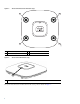
Access Point Ports and Connections (top) 2 1 A U AL BAN D D D U B D C U AL BAN D D D U 4 Antenna connector A 3 Antenna connector C 2 Antenna connector B 4 Antenna connector D Access Point LED Indicator (top) 1 1 LED indicator The ports and connections on the bottom of the access point are shown in Figure 3.
Figure 3 Access Point Ports and Connections (bottom) 1 5 6 272377 6 2 1 3 Kensington lock slot 4 4 Console port 5 Security padlock and hasp (padlock not included) DC Power connection 2 3 Gbit Ethernet port 6 Mounting bracket pins (feet for desk or table-top mount) 7 Configuring the Access Point This section describes how to connect the access point to a wireless LAN controller.
Note CAPWAP support is provided in controller software release 5.2 or later. However, your controller must be running release 7.2.110.0 or later to support 2600 series access points. Note You cannot edit or query any access point using the controller CLI if the name of the access point contains a space. Note Make sure that the controller is set to the current time.
Note Access points mounted in a building’s environmental airspace must be powered using PoE to comply with safety regulations. Cisco recommends that you make a site map showing access point locations so that you can record the device MAC addresses from each location and return them to the person who is planning or managing your wireless network.
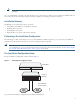
Step 1 Make sure that the Cisco wireless LAN controller DS port is connected to the network. Use the CLI, web-browser interface, or Cisco WCS procedures as described in the appropriate Cisco wireless LAN controller guide. a. Make sure that access points have Layer 3 connectivity to the Cisco wireless LAN controller Management and AP-Manager Interface. b. Configure the switch to which your access point is to attach.
Note When you are installing a Layer 3 access point on a different subnet than the Cisco wireless LAN controller, be sure that a DHCP server is reachable from the subnet on which you will be installing the access point, and that the subnet has a route back to the Cisco wireless LAN controller. Also be sure that the route back to the Cisco wireless LAN controller has destination UDP ports 5246 and 5247 open for CAPWAP communications.
8 Mounting the Access Point Cisco Aironet 2600 series access points can be mounted in several configurations, including on a suspended ceiling, on a hard ceiling or wall, on an electrical or network box, and above a suspended ceiling. Click this URL to browse to complete access point mounting instructions: http://www.cisco.com/en/US/docs/wireless/access_point/mounting/guide/apmount.
Using DHCP Option 43 You can use DHCP Option 43 to provide a list of controller IP addresses to the access points, enabling them to find and join a controller. For additional information, refer to the “Configuring DHCP Option 43 and DHCP Option 60” section on page 27. Checking the Access Point LED The location of the access point status LED is shown in Figure 5. Regarding LED status colors, it is expected that there will be small variations in color intensity and hue from unit to unit.
Table 1 LED Status Indications (continued) Message Type Status LED Message Meaning Operating status Blinking blue Software upgrade in progress Cycling through green, red, and off Discovery/join process in progress Rapidly cycling through blue, green, and red Access point location command invoked Blinking red Ethernet link not operational Blinking blue Configuration recovery in progress (MODE button pushed for 2 to 3 seconds) Red Ethernet failure or image recovery (MODE button pushed for 20
• Up to three times the maximum number of access points supported by the platform for the 2600 series controllers and the Controller Network Module within the Cisco 28/37/38xx Series Integrated Services Routers When the controller is maintaining join-related information for the maximum number of access points, it does not collect information for any more access points. An access point sends all syslog messages to IP address 255.255.255.
Models Certification Numbers AIR-CAP2602E-A-K9 AIR-CAP2602I-A-K9 AIR-SAP2602E-A-K9 AIR-SAP2602I-A-K9 LDK102080 AIR-CAP2602E-B-K9 AIR-CAP2602I-B-K9 AIR-SAP2602E-B-K9 AIR-SAP2602I-B-K9 AIR-AP2602I-UXK9 AIR-AP2602E-UXK9 Manufacturer: Cisco Systems, Inc. 170 West Tasman Drive San Jose, CA 95134-1706 USA This device complies with Part 15 rules. Operation is subject to the following two conditions: 1. This device may not cause harmful interference, and 2.
VCCI Statement for Japan Warning This is a Class B product based on the standard of the Voluntary Control Council for Interference from Information Technology Equipment (VCCI). If this is used near a radio or television receiver in a domestic environment, it may cause radio interference. Install and use the equipment according to the instruction manual.
2. If this equipment causes RF interference to a premises radio station of RF-ID, promptly change the frequency or stop using the device; contact the number below and ask for recommendations on avoiding radio interference, such as setting partitions. 3. If this equipment causes RF interference to a specified low-power radio station of RF-ID, contact the number below.
To reduce potential radio interference to other users, the antenna type and its gain should be so chosen that the equivalent isotropically radiated power (EIRP) is not more than that permitted for successful communication.
Declaration of Conformity with regard to the R&TTE Directive 1999/5/EC & Medical Directive 93/42/EEC 20
The following standards were applied: EMC—EN 301.489-1 v1.8.1; EN 301.489-17 v2.1.1 Health & Safety—EN60950-1: 2005; EN 50385: 2002 Radio—EN 300 328 v 1.7.1; EN 301.893 v 1.5.1 The conformity assessment procedure referred to in Article 10.4 and Annex III of Directive 1999/5/EC has been followed. This device also conforms to the EMC requirements of the Medical Devices Directive 93/42/EEC. Note This equipment is intended to be used in all EU and EFTA countries.
Declaration of Conformity for RF Exposure This section contains information on compliance with guidelines related to RF exposure. Generic Discussion on RF Exposure The Cisco products are designed to comply with the following national and international standards on Human Exposure to Radio Frequencies: • US 47 Code of Federal Regulations Part 2 Subpart J • American National Standards Institute (ANSI) / Institute of Electrical and Electronic Engineers / IEEE C 95.
The US Food and Drug Administration has stated that present scientific information does not indicate the need for any special precautions for the use of wireless devices. The FCC recommends that if you are interested in further reducing your exposure then you can easily do so by reorienting antennas away from the user or placing the antennas at a greater separation distance then recommended or lowering the transmitter power output.
• FCC Bulletin 56: Questions and Answers about Biological Effects and Potential Hazards of Radio Frequency Electromagnetic Fields • FCC Bulletin 65: Evaluating Compliance with the FCC guidelines for Human Exposure to Radio Frequency Electromagnetic Fields • FCC Bulletin 65C (01-01): Evaluating Compliance with the FCC guidelines for Human Exposure to Radio Frequency Electromagnetic Fields: Additional Information for Evaluating Compliance for Mobile and Portable Devices with FCC limits for Human Exposure to R
English Translation Administrative Rules for Low-power Radio-Frequency Devices Article 12 For those low-power radio-frequency devices that have already received a type-approval, companies, business units or users should not change its frequencies, increase its power or change its original features and functions.
English Translation Low-power Radio-frequency Devices Technical Specifications 4.7 Unlicensed National Information Infrastructure 4.7.5 Within the 5.25-5.35 GHz band, U-NII devices will be restricted to indoor operations to reduce any potential for harmful interference to co-channel MSS operations. 4.7.6 The U-NII devices shall accept any interference from legal communications and shall not interfere the legal communications.
Figure 6 Brazil Regulatory Information Portuguese Translation Este equipamento opera em caráter secundário, isto é, não tem direito a proteção contra interferência prejudicial, mesmo de estações do mesmo tipo, e não pode causar interferência a sistemas operando em caráter primário. English Translation This equipment operates on a secondary basis and consequently must accept harmful interference, including interference from stations of the same kind.
Note If your access point was ordered with the Service Provider Option (AIR-OPT60-DHCP) selected in the ordering tool, the VCI string for the access point contains ServiceProvider.
13 Access Point Specifications For the technical specifications of the 2600 series access points, see the Cisco Aironet 2600 Series Access Points Data Sheet at the following URL: http://www.cisco.com/c/en/us/products/collateral/wireless/aironet-2600-series/data_sheet_c78-709514.
Americas Headquarters Cisco Systems, Inc. San Jose, CA Asia Pacific Headquarters Cisco Systems (USA) Pte. Ltd. Singapore Europe Headquarters Cisco Systems International BV Amsterdam, The Netherlands Cisco has more than 200 offices worldwide. Addresses, phone numbers, and fax numbers are listed on the Cisco Website at www.cisco.com/go/offices. Printed in the USA on recycled paper containing 10% postconsumer waste.