
Design Guide

177
Cisco Aironet 1520, 1130, 1240 Series Wireless Mesh Access Points, Design and Deployment Guide, Release 6.0
OL-20213-01
Adding and Managing Mesh Access Points with Cisco WCS
• An amber dot represents an acceptable SNR (20-25 dB).
• A red dot represents a low SNR (below 20 dB).
• A black dot indicates a root access point.
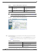
Using Mesh Filters to Modify Map Display of Maps and Mesh Links
In the mesh hierarchical window, you can also define mesh filters to determine which mesh access points
display on the map based on hop values as well as what labels display for mesh links.
Mesh access points are filtered by the number of hops between them and their root access point.
To use mesh filtering, follow these steps.
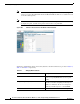
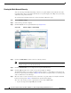
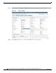
Step 1 To modify what label and color displays for a mesh link, follow these steps:
a. In the Mesh Parent-Child Hierarchical View, select an option from the Link Label drop-down
menu. Options are None, Link SNR, and Packet Error Rate.
b. In the Mesh Parent-Child Hierarchical View, select an option from the Link Color drop-down
menu to define which parameter (Link SNR or Packet Error Rate) determines the color of the
mesh link on the map.
Note The color of the link provides a quick reference point of the SNR strength or Packet Error Rate.
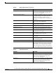
Table 28 Bridging Link Information
Parameter Description
Information fetched on Date and time that information was compiled.
Link SNR Link signal-to-noise ratio (SNR).
Link Type Hierarchical link relationship.
SNR Up Signal-to-noise radio for the uplink (dB).
SNR Down Signal-to-noise radio for the downlink (dB).
PER The packet error rate for the link.
Tx Parent Packets The TX packets to a node while acting as a parent.
Rx Parent Packets The RX packets to a node while acting as a parent.
Time of Last Hello Date and time of last hello.
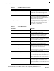
Table 29 Definition for SNR and Packet Error Rate Link Color
Link Color Link SNR Packet Error Rate (PER)
Green Represents a SNR above 25 dB (high
value)
Represents a PER of one percent (1%) or
lower