Cisco Aironet 1520, 1130, 1240 Series Wireless Mesh Access Points, Design and Deployment Guide, Release 6.0 Last revised: August 11, 2009 This document provides design and deployment guidelines for the deployment of secure enterprise, campus, and metropolitan Wi-Fi networks within the Cisco wireless mesh networking solution, a component of the Cisco Unified Wireless Network (CUWN).
Contents Contents Contents 2 Mesh Network Components 5 Mesh Access Points 5 Licensing for Indoor Mesh Access Points on a 5500 Series Controller Access Point Roles 5 Network Access 6 Network Segmentation 7 Cisco 1130 and 1240 Indoor Mesh Access Points 7 Cisco 1520 Series Outdoor Mesh Access Points 7 Cisco Wireless LAN Controllers 26 Cisco WCS 26 Mesh Deployment Modes 27 Wireless Mesh Network 27 Wireless Backhaul 28 5 Architecture Overview 29 CAPWAP 29 CAPWAP Discovery on a Mesh Network 29 Dynamic MTU De
Contents Wireless Propagation Characteristics 50 Wireless Mesh Mobility Groups 51 Increasing Mesh Availability 51 Indoor WLAN Network to Outdoor Mesh 53 Connecting the Cisco 1520 Series Mesh Access Point to Your Network 53 Upgrading to Release 6.
Contents Backhaul Algorithm 139 Passive Beaconing (Anti-Stranding) 139 DFS 141 Misconfiguration of BGN 145 Misconfiguration of the Mesh Access Point IP Address Misconfiguration of DHCP 147 Identifying the Node Exclusion Algorithm 147 Throughput Analysis 149 146 Adding and Managing Mesh Access Points with Cisco WCS 151 Adding Campus Maps, Outdoor Areas, and Buildings with Cisco WCS 151 Adding Campus Maps 151 Adding Outdoor Areas 152 Adding a Building to a Campus Map 153 Adding Mesh Access Points to Maps w
Mesh Network Components Mesh Network Components The Cisco wireless mesh network has four core components: • Cisco Aironet 1520, 1240, and 1130 Series mesh access points Note Cisco Aironet 1505 and 1510 mesh access points are not supported in this release.
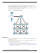
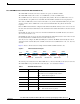
Mesh Network Components MAPs communicate among themselves and back to the RAP using wireless connections over the 802.11a radio backhaul. MAPs use the Cisco Adaptive Wireless Path Protocol (AWPP) to determine the best path through the other mesh access points to the controller. All the possible paths between the MAPs and RAPs form the wireless mesh network. Figure 1 shows the relationship between RAPs and MAPs in a mesh network.
Mesh Network Components • External RADIUS Authentication—Mesh access points can be externally authorized using a RADIUS server such as Cisco ACS (4.1 and later) that supports the client authentication type of Extensible Authentication Protocol-FAST (EAP-FAST) with certificates. Refer to the “Using the GUI to Enable External Authentication of Mesh Access Points” section on page 69.
Mesh Network Components AP1520s are available in a hazardous location hardware enclosure. When configured, the AP1520 complies with safety standards for Class I, Division 2, Zone 2 hazardous locations. Refer to the “Hardware Enclosure for Hazardous Conditions (AIR–LAP1522HZ–X–K9)” section on page 25 for more details. Note Refer to the Cisco Aironet 1520 Series Lightweight Outdoor Access Point Ordering Guide for power, mounting, antenna, and regulatory support by model: http://www.cisco.
Mesh Network Components Cisco 1524SB Mesh Access Point (Part No. AIR–LAP1524SB–X–K9) The AP1524SB is introduced in release 6.0 and can operate as a RAP or a MAP. The AP1524SB includes three radios: one 2.4-GHz radio, and two 5.8-GHz radios. The 2.4-GHz radio is for client access (non-public safety traffic). The two 5.8-GHz radios serves as serial backhauls: one uplink and one downlink. The AP1524SB is suitable for linear deployments. One of the 5.
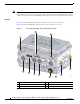
Mesh Network Components Note Depending on product model, the AP1524SB could have either 5.0-GHz radios or 5.8-GHz sub-band radios installed in slot 1 and slot 2. Regardless of the radios installed, the AP1524SB running controller software release 6.0 is restricted to the UNII-3 channels (149, 153, 157, 161, and 165) in slot 1 and slot 2. Hardware Figure 3 shows the AP1520 (all models) and its bottom connectors (radio side view).
Mesh Network Components 4 Fiber port (optional) 10 LEDs 5 Cable POC port (optional) 11 PoE in port 6 Aux/Console port Cisco 1520 Series Mesh Access Point (radio cover view) 203823 Figure 4 1 2 3 1 Antenna port 3 4 Ground screw holes 2 Antenna port 2 5 DC power connector 3 Antenna port 1 Note For details on antennas and their selection, refer to the “Antennas” section on page 19. Note For details on power, refer to the “Multiple Power Options” section on page 12.
Mesh Network Components • Port 0 (g0) is a Power over Ethernet (PoE) input port–PoE (in) • Port 1 (g1) is a PoE output port–PoE (out) • Port 2 (g2) is a cable connection • Port 3 (g3) is a fiber connection You can query the status of these four interfaces in the controller CLI and Cisco WCS. In the controller CLI, the show mesh env summary command is used to display the status of the ports.
Mesh Network Components Reset Button The access point has a reset button located on the bottom of the unit (see Figure 5). The reset button is recessed in a small hole that is sealed with a screw and a rubber gasket. The reset button is used to perform these functions: • Reset the access point—press the reset button for less than 10 seconds. LEDs turn off during the reset and then reactivate when the reset is complete. • Disable battery backup power—Press the reset button for more than 10 seconds.
Mesh Network Components To reset the access point, follow these steps: Step 1 Use a Phillips screwdriver to remove the reset button screw. Be careful not to loose the screw. Step 2 Use a straighten paperclip, and push the reset button for less than 10 seconds. This causes the access point to reboot (power cycle), all LEDs turn off for approximately 5 seconds and then the LEDs reactivate. Step 3 Replace the reset button screw, and use a Phillips screwdriver to tighten to 22 to 24 in. lbs (2.49 to 2.
Mesh Network Components 1 Status LED—access point and software status 3 RF-1 LED—Status of the radio in slot 0 (2.4-GHz) and slot 2 (5.8-GHz for 1524SB and 4.9-GHz for 1524PS)). 2 Uplink LED—Ethernet, cable, or fiber status 4 RF-2 LED—Status of the radio in slot 1 (5.8-GHz) and the radio in slot 3.1 1. Slot 3 is disabled in this release. Note The RF-1 and RF-2 LEDs monitor two radios simultaneously but do not identify the affected radio.
Mesh Network Components Table 2 Access Point LED Signals (continued) LED Color1,2 RF-2 Disabled in this release. Meaning Slot 3 1. If all LEDs are off, the access point has no power. 2. When the access point power supply is initially turned on, all LEDs are amber.
Mesh Network Components Note Frequency depends on the regulatory domain in which the access point is installed. For additional information, refer to the Channels and Power Levels document at: http://www.cisco.com/en/US/docs/wireless/access_point/channels/lwapp/reference/guide/lw_chp2.html Table 3 Frequency Band Frequency Band Terms UNII-1 1 Description Model Support Regulations for UNII devices operating in 1130, 1240 the 5.15 to 5.25 GHz frequency band.
Mesh Network Components Figure 8 Table 4 DFS and TPC Band Requirements Channels Requiring DFS by Regulatory Domain Regulatory Domain/ Channel (Frequency Band) -A -E -C -P -S -K -T 52 (5260 MHz) 56 (5280 MHz) Y Y 60 (5300 MHz) Y Y 64 (5320 MHz) Y Y 100 (5500 MHz) Y Y Y Y 104 (5520 MHz) Y Y Y Y 108 (5540 MHz) Y Y Y Y 112 (5560 MHz) Y Y Y Y 116 (5580 MHz) Y Y Y Y 120 (5600 MHz) Y Y Y 124 (5620 MHz) Y Y Y 128 (5640 MHz) Y Y 132 (5660 MHz) Y Y Y 136 (5
Mesh Network Components Antennas Overview Antenna choice is a vital component of any wireless network deployment. Essentially, two broad types of antenna exist: directional and omni-directional. Each type of antenna has a specific use and is most beneficial in specific types of deployments. Because antennas distribute RF signal in large lobed coverage areas determined by antenna design, successful coverage is heavily reliant on antenna choice.
Mesh Network Components Table 5 External 2.4- and 5-GHz Antennas (continued) Part Number Model AIR-ANT5180V-N Gain (dBi) 5-GHz compact omnidirectional 2 4.9-GHz compact omnidirectional AIR-ANT58G10SSA-N 8.0 3 5-GHz sector AIR-ANT5114P-N 4.9- to 5-GHz patch AIR-ANT5117S-N 7.0 9.5 2 14.0 4.9- to 5-GHz 90-degree sector 2 17.0 1. The compact omnidirectional antennas mount directly on the access point. 2. The compact omnidirectional antennas mount directly on the access point. 3.
Mesh Network Components Figure 9 Two Radio Cable Mesh Access Point Configuration (Hinged-side Facing Forward) 1 Clamp bracket with cable clamps (part of strand mount kit, ordered separately) 5 Cable bundle 2 5-Ghz antenna1 6 Fiber-optic connection2 3 2.4 GHz antennas2 7 Cable POC power input3 4 Strand support cable 8 Strand mount bracket (part of strand mount kit, ordered separately) 1. Illustration shows antenna for an access point with two radios. 2. Liquid tight connector not shown. 3.
Mesh Network Components Figure 10 Two Radio Fiber Mesh Access Point Configuration (Hinged-side Facing Backward) Cisco Aironet 1520, 1130, 1240 Series Wireless Mesh Access Points, Design and Deployment Guide, Release 6.
Mesh Network Components 1 Stainless steal mounting straps (part of pole mount kit) 4 2-4GHz antennas 2 2.4-GHz antenna 5 Pole (wood, metal, or fiberglass), 2 to 16 in. (5.1 to 40.6 cm) diameter 3 5-GHz antenna 6 Mounting bracket (part of pole mount kit) Figure 11 AP1524 Mesh Access Point Pole Mount Configuration (Hinged-side Facing Forward) Cisco Aironet 1520, 1130, 1240 Series Wireless Mesh Access Points, Design and Deployment Guide, Release 6.
Mesh Network Components 1 2.4-GHz antenna (Tx/Rx) 3 Fiber-optic connection 2 5-GHz antenna (Tx/Rx) 4 4.9-GHz antenna (Tx/Rx) Figure 12 shows one of the recommend installations of an outdoor AP1520.
Mesh Network Components Table 7 RX Sensitivities and MRC Gain (continued) Typical sensitivity (dBM) MRC gain Modulation Rate One antenna Two antennas MRC Three antennas MRC Two antennas Three antenna 6 -90.3 -90.3 -90.3 0.0 0.0 9 -90.3 -90.3 -90.3 0.0 0.0 12 -89.0 -89.5 -90.0 0.5 1.0 18 -88.0 -89.5 -90.0 1.5 2.0 24 -84.3 -87.0 -88.3 2.7 4.0 36 -81.3 -84.0 -85.8 2.7 4.5 48 -77.3 -80.0 -81.8 2.7 4.5 54 -76.0 -78.7 -80.5 2.7 4.
Mesh Network Components When you select the hazardous location option as part of the ordering process, Cisco configures the system to contain the new components. Two conduit adaptors and assembly instructions placed in the shipping box provide information and assembly procedures. No additional weatherproof enclosure is required to operate in temperature ranges of –40oC to +55oC.
Mesh Network Components With Cisco WCS, network administrators have a solution for RF prediction, policy provisioning, network optimization, troubleshooting, user tracking, security monitoring, and wireless LAN systems management. Graphical interfaces make wireless LAN deployment and operations simple and cost-effective. Detailed trending and analysis reports make Cisco WCS vital to ongoing network operations. Cisco WCS runs on a server platform with an embedded database.
Mesh Network Components The three RAPs are connected to the wired network at each location and are located on the building roof. All the downstream access points operate as MAPs and communicate using wireless links (not shown). Both MAPs and RAPs can provide WLAN client access; however, the location of RAPs are often not suitable for providing client access. Each of the three access points in Figure 15 are located on the building roofs and are functioning as RAPs.
Architecture Overview Wireless Backhaul AES Encrypted MAP WCS t tex Controller ar En cr y Cle pte d RAP 205683 Figure 16 Architecture Overview CAPWAP CAPWAP is the provisioning and control protocol used by the controller to manage access points (mesh and non-mesh) in the network. In release 5.2, CAPWAP replaces LWAPP. Upgrading from an earlier LWAPP release (4.1.x.x or earlier) to release 5.2 is transparent.
Architecture Overview 4. If both steps 2 and 3 fail and there is no successful CAPWAP connection to a controller, then the mesh access point falls back to LWAPP. 5. If no discovery occurs after attempting steps 2, 3 and 4, the mesh access point tries the next link. Dynamic MTU Detection If the MTU is changed in the network, the access point detects the new MTU value and forwards that to the controller to adjust to the new MTU.
Architecture Overview CLI commands with known keywords and proper syntax are converted to XML while improper CLI commands are ignored and saved to flash memory. Any field with an invalid value is filtered out and set to a default by the XML validation engine.Validation occurs during bootup. To see any ignored commands or invalid configuration values, enter this command: show invalid-config Note You can only execute this command before either the clear config or save config command.
Architecture Overview • Wireless mesh data frame flow. • AWPP exchanges. Because the CAPWAP model is well known and the AWPP is a proprietary protocol, only the wireless mesh data flow is described. The key to the wireless mesh data flow is the address fields of the 802.11 frames being sent between mesh access points. An 802.11 data frame can use up to four address fields: receiver, transmitter, destination, and source.
Architecture Overview Figure 18 Logical Bridge and WLAN Mapping Bridged Ethernet 205684 WLANs CAPWAP Tunnel Bridged Ethernet VLAN mapped to WLAN Mesh Neighbors, Parents, and Children Relationships among mesh access points are either as a parent, child or neighbor (see Figure 19). • A parent access point offers the best route back to the RAP based on its ease values. A parent can be either the RAP itself or another MAP. – Ease is calculated using the SNR and link hop value of each neighbor.
Architecture Overview Choosing the Best Parent AWPP follows the following process in selecting parents for a RAP or MAP with a radio backhaul: • A list of channels with neighbors is generated by passive scanning in the scan state, which is a subset of all backhaul channels. • The channels with neighbors are sought by actively scanning in seek state and the backhaul channel is changed to the channel with the best neighbor.
Design Considerations SNR Smoothing One of the challenges in WLAN routing is the ephemeral nature of RF. This must be considered when analyzing an optimal path and deciding when a change in path is required. The SNR on a given RF link can change substantially from moment to moment, and changing route paths based on these fluctuations results in an unstable network, with severely degraded performance.
Design Considerations Note To set the mesh backhaul bit rate for each access point, choose Wirless > Access Points > All APs, then click an AP name and click the Mesh tab. – The required minimum LinkSNR for backhaul links per data rate is shown in Table 9.
Design Considerations There is no current software limitation of how many MAPs per RAP you can configure. However, it is suggested that you limit this to 20 MAPs per RAP. • Number of controllers – The number of controllers per mobility group is limited to 72. • Number of mesh access points supported per controller. Refer to “Controller Planning”in the next section.
Site Preparation and Planning Mesh Access Point Support by Controller Model (continued) Local AP Support Controller Model (non-mesh)1 Maximum Possible Mesh AP Support RAPs MAPs Total Mesh AP Support 21122 12 1 11 12 3 9 12 6 6 12 9 3 12 12 0 12 1 24 25 5 20 25 10 15 25 15 10 25 20 5 25 25 0 25 1 374 375 100 275 375 250 100 350 300 0 300 2125 12 2 WiSM 25 3 300 25 375 1.
Site Preparation and Planning Note When power is not readily available, use an unrestricted power supply (UPS) to temporarily power the mesh link.
Site Preparation and Planning Determining Line of Sight When determining the suitability of a successful link, you need to define how far the link is expected to transmit and at what radio data rate. Very close links, one kilometer or less, are fairly easy to achieve assuming there is clear line of sight (LOS)–a path with no obstructions.
Site Preparation and Planning Point-to-Point Link Fresnel Zone Figure 22 Typical Obstructions in Fresnel Zone 148453 148452 Figure 21 It is possible to calculate the radius of the Fresnel zone (in feet) at any particular distance along the path using this equation: F1 = 72.
Site Preparation and Planning Fresnel Zone Size in Wireless Mesh Deployments To give an approximation of size of the maximum Fresnel zone to be considered, at a possible minimum frequency of 4.9 GHz, the minimum value changes depending on the regulatory domain. The minimum figure quoted is a possible band allocated for public safety in the US; and maximum distance of one mile gives a Fresnel zone of clearance requirement of 9.78 ft = 43.3 x SQR(1/(4*4.9)).
Site Preparation and Planning Both the hidden node problem and the exposed node problem are inherent to wireless mesh networks because mesh access points share the same backhaul channel. Because these two problems can affect the overall network performance, the Cisco mesh solution seeks to mitigate these two problems as much as possible. For example, the AP1520s have at least two radios: one for backhaul access on 5GHz channel and the other for 2.4GHz client access.
Site Preparation and Planning • For 2.4-GHz, the local access cell size radius is 600 feet. One cell size comes out to be 1.310 x 10⁶, so the there are 25 cells per square mile. (See Figure 27 and Figure 28.) Figure 25 Cell Radius of 1000 Feet and Access Point Placement for Non-Voice Mesh Networks 148463 1000 feet (typical distance) One square mile, 9 cells Figure 26 Path Loss Exponent 2.3 to 2.7 Path Loss exponent 2.3 to 2.7 802.
Site Preparation and Planning Figure 27 Cell Radius of 600 Feet and Access Point Placement for Non-Voice Mesh Networks 148465 600 feet (typical distance) One square mile, 25 cells Figure 28 Path Loss Exponent 2.5 to 3.0 Path Loss exponent 2.5 to 3.0 802.11g 2.4GHz coverage 1200 d(PL, 2.5, 2.45 d(PL, 2.7, 2.45 d(PL, 3.0, 2.45 . 10 ) . 10 ) .
Site Preparation and Planning The RAP shown in Figure 29 is simply a starting point. The goal is to use the RAP location in combination with RF antenna design to ensure that there is a good RF link to the MAPs within the core of the cell. This means that the physical location of the RAP can be on the edge of the cell, and a directional antenna is used to establish a link into the center of the cell.
Site Preparation and Planning Figure 30 Multiple RAP and MAP Cells Channel B2 Channel C2 148469 Channel D2 Choosing various channels reduces the co-channel interference at the cell boundaries, at the expense of faster mesh convergence, because MAPs must fall back to seek mode to find neighbors in adjacent cells. In areas of high traffic density, co-channel interference has the highest impact, and this is likely to be around the RAPs.
Site Preparation and Planning Figure 31 Laying out Various Cells B2 B4 C2 C3 148470 B3 C4 D2 D3 D4 If possible, the channel planning should also minimize channel overlap in cases where the mesh has expanded to cover the loss of a RAP connection, as shown in Figure 32.
Site Preparation and Planning Collocating AP1520s on Adjacent Channels If two collocated AP1520s are operating on adjacent channels such as channel 149 (5745 MHz) and channel 152 (5765 MHz), the minimum vertical separation between the two AP1520s is 40 feet. (This is true for mesh access points equipped with either 8 dBi omni-directional or 17 dBi high-gain directional patch antennas). If two collocated AP1520s are operating on channels 1, 6 or 11 (2412 to 2437 MHz) with a 5.
Site Preparation and Planning Figure 33 Note Cell Radius of 1000 Feet and Access Point Placement for Voice Mesh Networks Refer to “Guidelines For Using Voice On The Mesh Network” section on page 112 for additional voice considerations when configuring voice on your network. Wireless Propagation Characteristics Table 11 provides a comparison of the 2.4 GHz and 5 GHz bands. The 2.4 GHz band does provide better propagation characteristics than 5 GHz, but 2.
Site Preparation and Planning Wireless Mesh Mobility Groups Keep in mind that a wireless mesh network built using the maximum number of controllers in a mobility group is not truly the maximum size of WLAN coverage because this is simply the maximum size of the mobility group. The WLANs that are part of a mobility group can be replicated in another mobility group, and a WLAN client is able to roam between these mobility groups. Roaming between mobility groups is done at Layer 3 roaming.
Site Preparation and Planning Figure 34 Two RAPs per Cell with the Same Channel 148472 Channel B2 Figure 35 Two RAPs per Cell on Different Channels 148473 Channel B2 Cisco Aironet 1520, 1130, 1240 Series Wireless Mesh Access Points, Design and Deployment Guide, Release 6.
Connecting the Cisco 1520 Series Mesh Access Point to Your Network Multiple RAPs If multiple RAPs are to be deployed, the purpose for deploying these RAPs needs to be considered. If the RAPs are being deployed to provide hardware diversity, the additional RAP(s) should be deployed on the same channel as the primary RAP to minimize the convergence time in a scenario where the mesh transfers from one RAP to another. When planning RAP hardware diversity, the 32 MAPs per RAP limitation should be remembered.
Connecting the Cisco 1520 Series Mesh Access Point to Your Network Mesh Network Traffic Termination Network - CAPWAP Bridged 205685 Figure 36 Upgrading to Release 6.0 Mesh and Mainstream Releases on the Controller After controller release 4.1.185.0, all mesh features were extracted from the main software base and a new mesh release software base for the controller was created. This mesh software base remained distinct from the main software base of the controller until release 5.2. In release 5.
Connecting the Cisco 1520 Series Mesh Access Point to Your Network Mesh and Mainstream Controller Software Releases Mainstream Controller Releases 4.1.185.0 1505 1510 1000 1230 1120 1240 1130 1310 4.2 1000 1230 1120 1240 1130 1250 1310 4.2.x MR 1000 1230 1120 1240 1130 1250 1310 1000 1230 1120 1240 1130 1250 1310 4.2.176.51M 5.0 1230 1120 1240 5.1 1130 1250 1230 1310 1120 1240 1130 1250 1310 Mesh Controller Releases 4.1.191.24M 4.1.190.5 1505 1510 1522 -US, Can 4.2.173.0 4.2.176.
Connecting the Cisco 1520 Series Mesh Access Point to Your Network Caution Upgrade to release 5.2 from the latest 4.1.192.xxM mesh release prior to upgrading to release 6.0. Upgrading directly to release 5.2 from either 4.1.190.05 or 4.1.191.22M is not supported. For details on upgrading to latest version of 4.1.192.xxM from an earlier mesh release, refer to the “Upgrade Compatibility Matrix” in the Release Notes for Cisco Wireless LAN Controllers and Mesh Access Points for Release 4.1.192.
Connecting the Cisco 1520 Series Mesh Access Point to Your Network j. Read Cisco’s End User Software License Agreement and then click Agree. k. Save the file to your hard drive. Step 3 Copy the controller software file (filename.aes) and the boot image to the default directory on your TFTP server. Step 4 Click Commands > Download File to open the Download File to Controller window. Step 5 From the File Type drop-down box, choose Code.
Connecting the Cisco 1520 Series Mesh Access Point to Your Network a. Configure a backup controller. Refer to “Configuring Backup Controllers” procedure on page 63. 5. Configure external authentication of MAC addresses using an external RADIUS server. Refer to the “Configuring External Authentication and Authorization Using a RADIUS Server” section on page 68. 6. Configure global mesh parameters. Refer to the “Configuring Global Mesh Parameters” section on page 71. 7. Configure local mesh parameters.
Connecting the Cisco 1520 Series Mesh Access Point to Your Network Figure 38 Step 2 Click New. The MAC Filters > New window appears (see Figure 39). Figure 39 Step 3 MAC Filtering Window MAC Filters > New Window Enter the MAC address of the mesh access point. Note For 1522, 1524PS, and 1524SB outdoor mesh access points, enter the BVI MAC address of the mesh access point into the controller as a MAC filter. For 1130 and 1240 indoor mesh access points, enter the Ethernet MAC.
Connecting the Cisco 1520 Series Mesh Access Point to Your Network Step 6 From the Interface Name drop-down box, choose the controller interface to which the mesh access point is to connect. Step 7 Click Apply to commit your changes. The mesh access point now appears in the list of MAC filters on the MAC Filtering window. Step 8 Click Save Configuration to save your changes. Step 9 Repeat this procedure to add the MAC addresses of additional mesh access points to the list.
Connecting the Cisco 1520 Series Mesh Access Point to Your Network Using the GUI to Configure the AP Role To configure the role of a mesh access point using the GUI, follow these steps: Step 1 Click Wireless to open the All APs page. Step 2 Click the name of an access point. The All APs > Details (General) page appears. Step 3 Click the Mesh tab (see Figure 40). Figure 40 All APs > Details for (Mesh) Page Step 4 Choose RootAP or MeshAP from the AP Role drop-down box.
Connecting the Cisco 1520 Series Mesh Access Point to Your Network Step 4 Verify that the LWAPP Transport Modes is set to Layer 3. If it is not, change it to Layer 3 and click Apply. Step 5 Save any changes. Step 6 From the menu bar, click Monitor to return to the Monitor summary window. Step 7 Proceed to the “Configuring Multiple Controllers Using DHCP 43 and DHCP 60” section on page 62 to assign a primary, secondary and tertiary controller.
Connecting the Cisco 1520 Series Mesh Access Point to Your Network Configuring Backup Controllers A single controller at a centralized location can act as a backup for mesh access points when they lose connectivity with the primary controller in the local region. Centralized and regional controllers need not be in the same mobility group.
Connecting the Cisco 1520 Series Mesh Access Point to Your Network Figure 41 Note Global Configuration Window The fast heartbeat timer is not supported on mesh access points. Step 2 In the AP Primary Discovery Timeout field, enter a value between 30 and 3600 seconds (inclusive) to configure the access point primary discovery request timer. The default value is 120 seconds.
Connecting the Cisco 1520 Series Mesh Access Point to Your Network c. Click the High Availability tab. (See Figure 42.) Figure 42 d. If desired, enter the name and IP address of the primary backup controller for this access point in the Primary Controller fields. Note Step 7 All APs > Details for (High Availability) Window Entering an IP address for the backup controller is optional in this step and the next two steps.
Connecting the Cisco 1520 Series Mesh Access Point to Your Network Note Step 2 The controller_ip_address parameter in this command and the next two commands is optional. If the backup controller is outside the mobility group to which the mesh access point is connected (the primary controller), then you need to provide the IP address of the primary, secondary, or tertiary controller, respectively.
Connecting the Cisco 1520 Series Mesh Access Point to Your Network Information similar to the following appears for the show ap config general Cisco_AP command: Cisco AP Identifier.............................. Cisco AP Name.................................... Country code..................................... Regulatory Domain allowed by Country............. AP Country code.................................. AP Regulatory Domain............................. Switch Port Number ..............................
Connecting the Cisco 1520 Series Mesh Access Point to Your Network Configuring External Authentication and Authorization Using a RADIUS Server External authorization and authentication of mesh access points using a RADIUS server such as Cisco ACS (4.1 and later) is supported in release 5.2 and later. The RADIUS server must support the client authentication type of EAP-FAST with certificates.
Connecting the Cisco 1520 Series Mesh Access Point to Your Network Note For additional configuration details on Cisco ACS servers, refer to the following links: http://www.cisco.com/en/US/products/sw/secursw/ps2086/products_installation_and_configuration_gu ides_list.html (Windows) http://www.cisco.
Connecting the Cisco 1520 Series Mesh Access Point to Your Network Step 1 In the controller GUI, click Wireless > Mesh. The Mesh window appears (see Figure 43). Figure 43 Mesh Window Step 2 In the security section, select the EAP option from the Security Mode drop-down menu. Step 3 Check the Enabled check boxes for the External MAC Filter Authorization and Force External Authentication options. Step 4 Click Apply. Step 5 Click Save Configuration.
Connecting the Cisco 1520 Series Mesh Access Point to Your Network Configuring Global Mesh Parameters This section provides instructions for configuring the mesh access point to establish a connection with the controller including: • Setting the maximum range between RAP and MAP (not applicable to AP1130 and AP1240) • Enabling a backhaul to carry client traffic • Defining if VLAN tags are forwarded or not • Defining the authentication mode (EAP or PSK) and method (local or external) for mesh access
Connecting the Cisco 1520 Series Mesh Access Point to Your Network . Table 12 Global Mesh Parameters Parameter Description Range (RootAP to MeshAP) The optimum distance (in feet) that should exist between the root access point (RAP) and the mesh access point (MAP). This global parameter applies to all mesh access points when they join the controller and all existing mesh access points in the network.
Connecting the Cisco 1520 Series Mesh Access Point to Your Network Table 12 Global Mesh Parameters (continued) Parameter Description VLAN Transparent This feature determines how a mesh access point handles VLAN tags for Ethernet bridged traffic. Note Refer to the “Configuring Advanced Features” section on page 97 for overview and additional configuration details. If VLAN Transparent is enabled, then VLAN tags are not handled and packets are bridged as untagged packets.
Connecting the Cisco 1520 Series Mesh Access Point to Your Network Table 12 Global Mesh Parameters (continued) Parameter Description External MAC Filter Authorization MAC filtering uses the local MAC filter on the controller by default. When external MAC filter authorization is enabled, if the MAC address is not found in the local MAC filter, then the MAC address in the external RADIUS server is used.
Connecting the Cisco 1520 Series Mesh Access Point to Your Network Step 3 Click Apply to commit your changes. Step 4 Click Save Configuration to save your changes. Using the CLI to Configure Global Mesh Parameters Follow these steps to configure global mesh parameters including authentication methods using the controller CLI.
Connecting the Cisco 1520 Series Mesh Access Point to Your Network config mesh security force-ext-auth enable d.
Connecting the Cisco 1520 Series Mesh Access Point to Your Network Mesh Multicast Mode.............................. In-Out Mesh Full Sector DFS............................. enabled Mesh Ethernet Bridging VLAN Transparent Mode..... enabled Configuring Local Mesh Parameters After configuring global mesh parameters, you must configure the following local mesh parameters for these specific features if in use in your network: • Ethernet Bridging.
Connecting the Cisco 1520 Series Mesh Access Point to Your Network Point-to-Multipoint Bridging 148439 Figure 45 Using the GUI to Enable Ethernet Bridging To enable Ethernet Bridging on a RAP or MAP using the GUI, follow these steps: Step 1 Click Wireless > All APs. Step 2 Click the AP name link of the mesh access point on which you want to enable Ethernet bridging. Step 3 At the details window, select the Mesh tab. (See Figure 46.
Connecting the Cisco 1520 Series Mesh Access Point to Your Network • RootAP—Select this option if the AP1520 has a wired connection to the controller. Note At least one mesh access point must be set to RootAP in the mesh network. Step 5 To assign this mesh access point to a bridge group, enter a name for the group in the Bridge Group Name field. Step 6 Check the Ethernet Bridging check box to enable Ethernet bridging or uncheck it to disable this feature.
Connecting the Cisco 1520 Series Mesh Access Point to Your Network (Cisco controller) > show ap config general AP_Name Information similar to the following displays to the screen. Verifying BGN Using the GUI To verify BGN using the GUI, follow these steps: Step 1 Click Wireless > Access Points > AP Name. the details window for the selected mesh access point appears. Step 2 Click the Mesh tab. Details for the mesh access point including BGN appears. (See Figure 47.
Connecting the Cisco 1520 Series Mesh Access Point to Your Network Figure 47 AP Name > Mesh Configuring Workgroup Bridges A workgroup bridge (WGB) is used to connect wired networks over a single wireless segment. It does this by informing the mesh access point of all the clients that the WGB has on its wired segment via IAPP messages. In addition to the IAPP control messages, the data packets for WGB clients contains an extra MAC address in the 802.
Connecting the Cisco 1520 Series Mesh Access Point to Your Network Note Refer to the “Cisco Workgroup Bridges” section in Chapter 7 of the Cisco Wireless LAN Controller Configuration Guide, Release 6.0 for configuration steps at: http://www.cisco.com/en/US/products/ps6366/products_installation_and_configuration_guides_list.html Supported Workgroup Bridge Modes and Capacities • The 1130, 1240, and 1310 autonomous mesh access points must be running Cisco IOS release 12.
Connecting the Cisco 1520 Series Mesh Access Point to Your Network Figure 50 WPA-2 Security Settings for WGB To view the status of a WGB client, follow these steps: Step 1 Click Monitor > Clients. Step 2 At the client summary window, click on the MAC address of the client or search for the client using its MAC address. Step 3 In the window that appears, note that the client type is identified as WGB (far right). (See Figure 51.
Connecting the Cisco 1520 Series Mesh Access Point to Your Network Figure 52 Monitor > Clients > Detail Window (Wireless WGB Client) Figure 53 Monitor > Clients > Detail Window (Wired WGB Client) Configuring Public Safety Band Settings A public safety band (4.9-GHz) is supported on the AP1522 and AP1524PS. (See Figure 54.) Cisco Aironet 1520, 1130, 1240 Series Wireless Mesh Access Points, Design and Deployment Guide, Release 6.
Connecting the Cisco 1520 Series Mesh Access Point to Your Network Figure 54 • AP 1524PS Diagram Showing Radio Placement For the AP1524PS, the 4.9-GHz radio is independent of 5-GHz radio and is not used for the backhaul. On the AP1524PS, the 4.9-GHz band is enabled by default. – In Japan, 4.9 GHz is enabled by default as 4.9 GHz is unlicensed. • For AP1522s, you can enable the 4.9 GHz public safety band on the backhaul.
Connecting the Cisco 1520 Series Mesh Access Point to Your Network Figure 55 • Public Safety Warning During Configuration To verify that a public safety band is on the mesh access point using the CLI, enter: (Cisco controller) show mesh public-safety Global Public Safety status: enabled • To verify that a public safety band is on the mesh access point using the GUI: Wireless > Access Points > 802.
Connecting the Cisco 1520 Series Mesh Access Point to Your Network 4. Model c3205 is a Cisco 3200 with a 802.11a radio (5.8-GHz sub-band). Table 14 identifies mesh access points and their respective frequency bands that support WGB. Table 14 WGB Interoperability Chart RAP/MAP (5-GHz Backhaul) WGB 3200 1240 1130 1310 4.9-GHz (5, 10, 20 MHz) 5-GHz 2.4-GHz 5-GHz 2.4-GHz 5-GHz 2.4-GHz 2.
Connecting the Cisco 1520 Series Mesh Access Point to Your Network Using the GUI to Enable AP1522 and AP1524PS to Associate with Cisco 3200 To enable AP1522 and AP1524PS to associate with Cisco 3200, follow these steps. Step 1 To enable the backhaul for client access, click Wireless > Mesh to access the Mesh window. Step 2 Check the Backhaul Client Access Enabled check box to allow wireless client association over the 802.11a radio. Click Apply.
Connecting the Cisco 1520 Series Mesh Access Point to Your Network Using the CLI to Enable 1522 and 1524PS Association with Cisco 3200 To enable an AP1522 or AP1524PS to associate with Cisco 3200, follow these steps.
Connecting the Cisco 1520 Series Mesh Access Point to Your Network Using the GUI to Configure Power and Channels Settings To configure power and channel using the controller GUI, follow these steps. Step 1 From the Controller GUI, click Wireless > Access Points > 802.11a/n (see Figure 57). Figure 57 Note Step 2 In Figure 57, radio slots are displayed for each radio. For an AP1524SB, the 802.11a radio will display for slots 1 and 2 that operate on the 5.8-GHz band. For an AP1524PS, the 802.
Connecting the Cisco 1520 Series Mesh Access Point to Your Network Note Step 4 When assigning a channel to the AP1524SB, choose the Custom assignment method, and select one of the supported channels for the 5.8-GHz band: 149, 153, 157, 161, or 165. Assign Tx power levels (global and custom) for the radio. There are five selectable power levels for the 802.11a backhaul for AP1520s. • AP1522 supports ISM, UNII-2 band and UNII-2 Extended bands. • AP1524 supports the ISM band (5.8 GHz).
Connecting the Cisco 1520 Series Mesh Access Point to Your Network Step 3 To display the configurations on the mesh access points, enter these commands: • show mesh path MAP Information similar to the following appears: AP Name/Radio ----------------MAP1SB RAPSB RAPSB • Channel Rate Link-Snr Flags ------- ---- -------- ------161 auto 60 153 auto 51 is a Root AP.
Connecting the Cisco 1520 Series Mesh Access Point to Your Network Using the GUI to Configure Antenna Gain To configure antenna parameters using the controller GUI, follow these steps. Step 1 Click Wireless > Access Points > Radio > 802.11a/n to open the 802.11a/n Radios window. Step 2 For the mesh access point antenna you want to configure, hover over the blue arrow (far right) to display antenna options. Choose Configure. (See Figure 60.) Note Only external antennas have configurable gain settings.
Connecting the Cisco 1520 Series Mesh Access Point to Your Network Step 4 Click Apply and Save Configuration to save the changes. Using the CLI to Configure Antenna Gain Enter this command to configure antenna gain for the 802.11a backhaul radio using the controller CLI. config 802.11a antenna extAntGain antenna_gain AP_name where gain is entered in 0.5 dBm units (for example, 2.5 dBm =5).
Connecting the Cisco 1520 Series Mesh Access Point to Your Network Figure 62 Step 3 Choose one of the following options from the Channel Assignment Method drop-down box to specify the controller’s DCA mode: • Automatic—Causes the controller to periodically evaluate and, if necessary, update the channel assignment for all joined mesh access points. This is the default value.
Connecting the Cisco 1520 Series Mesh Access Point to Your Network Step 5 From the AnchorTime drop-down box, choose a number to specify the time of day when the DCA algorithm is to start. The options are numbers between 0 and 23 (inclusive) representing the hour of the day from 12:00 a.m. to 11:00 p.m. Step 6 Check the Avoid Foreign AP Interference check box to cause the controller’s RRM algorithms to consider 802.
Connecting the Cisco 1520 Series Mesh Access Point to Your Network Step 11 In the DCA Channel List section, the DCA Channels field shows the channels that are currently selected. To choose a channel, check its check box in the Select column. To exclude a channel, uncheck its check box. Range: 802.11a—36, 40, 44, 48, 52, 56, 60, 64, 100, 104, 108, 112, 116, 132, 136, 140, 149, 153, 157, 161, 165, 190, 196 802.11b/g—1, 2, 3, 4, 5, 6, 7, 8, 9, 10, 11 Default: 802.
Connecting the Cisco 1520 Series Mesh Access Point to Your Network • “Enabling Mesh Multicast Containment for Video” section on page 118 Configuring Ethernet VLAN Tagging Ethernet VLAN tagging allows specific application traffic to be segmented within a wireless mesh network and then forwarded (bridged) to a wired LAN (access mode) or bridged to another wireless mesh network (trunk mode).
Connecting the Cisco 1520 Series Mesh Access Point to Your Network Ethernet Port Notes • Ethernet VLAN tagging allows Ethernet ports to be configured as normal, access, or trunk in both indoor and outdoor implementations. When VLAN Transparent is disabled, the default Ethernet port mode is normal. VLAN Transparent must be disabled for VLAN tagging to operate and to allow configuration of Ethernet ports.
Connecting the Cisco 1520 Series Mesh Access Point to Your Network Figure 64 • Wireless > Mesh Window VLAN tagging can only be configured on Ethernet interfaces. – On AP1520s, three of the four ports can be used as secondary Ethernet interfaces: port 0-PoE in, port 1-PoE out, and port 3- fiber. Port 2 - cable cannot be configured as a secondary Ethernet interface. – In Ethernet VLAN tagging, port 0-PoE in on the RAP is used to connect to the trunk port of the switch of the wired network.
Connecting the Cisco 1520 Series Mesh Access Point to Your Network Figure 65 • Warning Message Displays for Backhaul Configuration Attempts No configuration is required to support VLAN tagging on any 802.11a backhaul Ethernet interface within the mesh network. – This includes the RAP uplink Ethernet port. The required configuration happens automatically using a registration mechanism. – Any configuration changes to an 802.11a Ethernet link acting as a backhaul are ignored and a warning results.
Connecting the Cisco 1520 Series Mesh Access Point to Your Network VLAN Registration To support a VLAN on an mesh access point, all the uplink mesh access points must also support the same VLAN. It is required for the segregation of traffic belonging to different VLANs. The activity by which an mesh access point communicates its requirements for a VLAN and gets response from a parent is known as VLAN registration. Note VLAN registration occurs automatically. No user intervention is required.
Connecting the Cisco 1520 Series Mesh Access Point to Your Network To enable VLAN tagging on a RAP or MAP using the GUI, follow these steps. Step 1 After enabling Ethernet Bridging, click Wireless > All APs. Step 2 Click the AP name link of the mesh access point on which you want to enable VLAN tagging. Step 3 At the details window, select the Mesh tab. (See Figure 66.) Figure 66 Step 4 All APs > Details for (Mesh) Window Click the Ethernet Bridging check box to enable the feature and click Apply.
Connecting the Cisco 1520 Series Mesh Access Point to Your Network Figure 67 2. VLAN Access Mode If configuring a RAP or MAP trunk port, click gigabitEthernet0 (port 0-PoE in). a. Select trunk from the mode drop-down menu. (See Figure 68.) b. Enter a native VLAN ID for incoming traffic. The native VLAN ID can be any value between 1 and 4095. Do not assign any value assigned to a user-VLAN (access). c. Click Apply.
Connecting the Cisco 1520 Series Mesh Access Point to Your Network Using the CLI to Configure Ethernet VLAN Tagging • To configure a MAP access port, enter this command: config ap ethernet 1 mode access enable AP1520-MAP 50 where AP1520-MAP is the variable AP_name and 50 is the variable access_vlan ID • To configure a RAP or MAP trunk port, enter this command: config ap ethernet 0 mode trunk enable AP1520-MAP 60 where AP1520-MAP is the variable AP_name and 60 is the variable native_vlan ID – To add a VL
Connecting the Cisco 1520 Series Mesh Access Point to Your Network • To see if VLAN transparent mode is enabled or disabled, enter the following command: Client Roaming High-speed roaming of Cisco Compatible Extension (CX), version 4 (v4) clients is supported at speeds up to 70 mph in outdoor mesh deployments of AP1522s and AP1524s. An example application might be maintaining communication with a terminal in an emergency vehicle as it moves within a mesh public network.
Connecting the Cisco 1520 Series Mesh Access Point to Your Network Note Client roaming is enabled by default. Configuring Voice Parameters in Indoor Mesh Networks You can configure call admission control (CAC) and QoS on the controller to manage voice and video quality on the mesh network. The indoor mesh access points (1130 and 1240) are 802.11e capable, and QoS is supported on the local 2.4-GHz access radio and the 5-GHz backhaul radio.
Connecting the Cisco 1520 Series Mesh Access Point to Your Network The collision avoidance mechanism uses two values, called CWmin and CWmax. CW stands for contention window. The CW determines what additional amount of time an endpoint should wait, after the interframe space (IFS), to attend to transmit a packet.
Connecting the Cisco 1520 Series Mesh Access Point to Your Network All backhaul frames are treated identically, regardless of whether they are MAP to MAP, RAP to MAP, or MAP to RAP. Encapsulating Mesh Traffic RAP Mesh Header MAP Bridging Packet CAPWAP Mesh 802.1/802.1P IP/IP DSCP Encapsulation Header CAPWAP Control/Data 205687 Figure 70 Queuing on the Mesh Access Point The mesh access point uses a high speed CPU to process ingress frames, Ethernet, and wireless on a first-come first-serve basis.
Connecting the Cisco 1520 Series Mesh Access Point to Your Network Controller to RAP Path 802.1p UP Outer IP DSCP Outer CAPWAP Encapsulation Incoming 802.1p UP IP DSCP Inner 205688 Figure 71 For CAPWAP control traffic the IP DSCP value is set to 46, and the 802.1p user priority is set to 7. Prior to transmission of a wireless frame over the backhaul, regardless of node pairing (RAP/MAP) or direction, the DSCP value in the outer header is used to determine a backhaul priority.
Connecting the Cisco 1520 Series Mesh Access Point to Your Network MAP to RAP Path IP DSCP Outer CAPWAP Encapsulation Incoming 802.11e UP IP DSCP Inner 205689 Figure 72 The minimum of the incoming 802.11e user priority and the WLAN override priority is translated using the information listed in Table 18 to determine the DSCP value of the IP frame.
Connecting the Cisco 1520 Series Mesh Access Point to Your Network Bridging Packets from and to a LAN Packets received from a station on a LAN are not modified in any way. There is no override value for the LAN priority. Therefore, in bridging mode the LAN must be properly secured. The only protection offered to the mesh backhaul is that non-CAPWAP control frames that map to the platinum queue are demoted to the gold queue.
Connecting the Cisco 1520 Series Mesh Access Point to Your Network • On the 802.11a or 802.11b/g/n > Voice parameters window: – Load-based CAC must be disabled – Enable admission control (ACM) for CCXv4 or v5 clients that have WMM enabled. Otherwise, bandwidth-based CAC does not operate properly. – Set the maximum RF bandwidth to 50% – Set the reserved roaming bandwidth to 6% – Enable traffic stream metrics • On the 802.11a or 802.
Connecting the Cisco 1520 Series Mesh Access Point to Your Network Table 20 Actual Calls Possible In A Clean Ideal Environment1 No of calls 802.11a radio 802.11b radio RAP 12 12 MAP1 7 10 MAP2 4 8 1. Traffic was bidirectional 64K voice flows. VoCoder type: G.711, PER <= 1%. Network setup was daisy-chained with no calls traversing more than 2 hops. No external interference. While making a call, observe the MOS score of the call on the 7921 phone. A MOS score between 3.5 and 4 is acceptable.
Connecting the Cisco 1520 Series Mesh Access Point to Your Network Figure 73 Mesh Network Example RAP 01 MESH MAP 01 MESH MAP 02 MESH MESH 802.11A 802.
Connecting the Cisco 1520 Series Mesh Access Point to Your Network • To view the mesh tree topology for the network and the bandwidth utilization (used/maximum available) of voice calls and video links for each mesh access point and radio, enter this command: show mesh cac bwused {voice | video} AP_name Information similar to the following appears: AP Name Slot# ------------- ------SB_RAP1 0 1 |SB_MAP1 0 1 || SB_MAP2 0 1 ||| SB_MAP3 0 1 • Radio ----11b/g 11a 11b/g 11a 11b/g 11a 11b/g 11a BW Used/Max --
Connecting the Cisco 1520 Series Mesh Access Point to Your Network • To view the mesh tree topology for the network and display the voice calls that are in progress, enter this command: show mesh cac callpath AP_name Information similar to the following appears: AP Name ------------SB_RAP1 | SB_MAP1 || SB_MAP2 ||| SB_MAP3 Note • Slot# ------0 1 0 1 0 1 0 1 Radio ----11b/g 11a 11b/g 11a 11b/g 11a 11b/g 11a Calls ----0 1 0 1 1 1 0 0 The calls column for each mesh access point radio in a call path
Connecting the Cisco 1520 Series Mesh Access Point to Your Network • To view the number of bronze, silver, gold, platinum, and management queues active on the specified access point. The peak and average length of each queue are shown as well as the overflow count. show mesh queue-stats AP_name Information similar to the following appears: Queue Type Overflows Peak length Average length ---------- --------- ----------- -------------Silver 0 1 0.000 Gold 0 4 0.004 Platinum 0 4 0.001 Bronze 0 0 0.
Connecting the Cisco 1520 Series Mesh Access Point to Your Network Note If 802.11b clients need to receive CAPWAP multicasts, then multicast must be enabled globally on the controller as well as on the mesh network (using the config network multicast global enable CLI command). If multicast does not need to extend to 802.11b clients beyond the mesh network, the global multicast parameter should be disabled (using the config network multicast global disable CLI command).
Checking the Health of the Network Checking the Health of the Network Show Mesh Commands The show mesh commands are grouped under the following headings: • Viewing General Mesh Network Details, page 120 • Viewing Mesh Access Point Details, page 122 • Viewing Public Safety Setting, page 124 • Viewing Security Settings and Statistics, page 124 To view a summary of possible show mesh commands, enter this command: (Cisco Controller) >show mesh ? env Show mesh environment.
Checking the Health of the Network SB_MAP2 SB_MAP3 42/107 36/96 OFF OFF DnDnNANA DnDnNANA N/A N/A controller >show mesh env SB_RAP1 AP Name.......................................... SB_RAP1 AP Model......................................... AIR-LAP1522AG-A-K9 AP Role.......................................... RootAP Temperature...................................... 39 C, 102 F Heater........................................... OFF Backhaul.........................................
Checking the Health of the Network • show mesh ap tree: Displays mesh access points within a tree structure (hierarchy). (Cisco Controller) >show mesh ap tree R1(0,y1) |-R2(1,y1) |-R6(2,y1) |-H2(1,default) Number of Mesh APs............................... 4 Number of RAPs................................... 1 Number of MAPs...................................
Checking the Health of the Network • show ap slots–Displays slot information for mesh access points. (Cisco Controller) > show ap slots Number of APs.................................... 3 AP Name Slots AP Model Slot0 Slot1 Slot2 Slot3 -------------------------------- ------ ------- ----------R1 2 LAP1520 802.11A 802.11BG H1 3 AIR-LAP1521AG-A-K9 802.11BG 802.11A 802.11A H2 4 AIR-LAP1521AG-A-K9 802.11BG 802.11A 802.11A 802.
Checking the Health of the Network Viewing DFS Details • show mesh dfs history–Displays a history of radar detections by channels and resulting outages. (Cisco Controller) > show mesh dfs history ap1520#show mesh dfs history Channel 100 detects radar and is unusable (Time Elapsed: 18 day(s), 22 hour(s), 10 minute(s), 24 second(s)). Channel is set to 136 (Time Elapsed: 18 day(s), 22 hour(s), 10 minute(s), 24 second(s)).
Checking the Health of the Network -------------------------Association Failures 0 Association Timeouts 0 Association Successes 0 Authentication Failures 0 Authentication Timeouts 0 Authentication Successes 0 Re-Association Failures 0 Re-Association Timeouts 0 Re-Association Successes 0 Re-Authentication Failures 0 Re-Authentication Timeouts 0 Re-Authentication Successes 0 Viewing Mesh Statistics for a Mesh Access Point This section explains how to use the controller GUI or CLI to view mesh statistics for
Checking the Health of the Network Figure 75 All APs > Access Point Name > Statistics Window This window shows the role of the mesh access point in the mesh network, the name of the bridge group to which the mesh access point belongs, the backhaul interface on which the access point operates, and the number of the physical switch port. It also displays a variety of mesh statistics for this mesh access point. Table 22 describes each of the statistics.
Checking the Health of the Network Table 22 Mesh Access Point Statistics Statistics Parameter Description Mesh Node Stats Malformed Neighbor Packets The number of malformed packets received from the neighbor. Examples of malformed packets include malicious floods of traffic such as malformed or short DNS packets and malformed DNS replies. Poor Neighbor SNR Reporting The number of times the signal-to-noise ratio falls below 12 dB on the backhaul link.
Checking the Health of the Network Table 22 Mesh Access Point Statistics (continued) Statistics Parameter Description Mesh Node Security Stats Transmitted Packets The number of packets transmitted during security negotiations by the selected mesh access point. Received Packets The number of packets received during security negotiations by the selected mesh access point.
Checking the Health of the Network Table 22 Mesh Access Point Statistics (continued) Statistics Parameter Description Mesh Node Security Stats (continued) Unknown Reauthentication Requests The number of unknown reauthentication requests received by the parent mesh access point node from its child. This state may occur when a child mesh access point is an unknown neighbor.
Checking the Health of the Network Re-Association Successes 0 Re-Authentication Failures 0 Re-Authentication Timeouts 0 Re-Authentication Successes 0 • To view the number of packets in the queue by type, enter this command: show mesh queue-stats AP_name Information similar to the following appears: Queue Type Overflows Peak length Average length ---------- --------- ----------- -------------Silver 0 1 0.000 Gold 0 4 0.004 Platinum 0 4 0.001 Bronze 0 0 0.000 Management 0 0 0.
Checking the Health of the Network Step 2 To view neighbor statistics for a specific mesh access point, hover your cursor over the blue drop-down arrow for the desired mesh access point and choose Neighbor Information. The All APs > Access Point Name > Neighbor Info window for the selected mesh access point appears (see Figure 77). Figure 77 All APs > Access Point Name > Neighbor Info Window This window lists the parent, children, and neighbors of the mesh access point.
Checking the Health of the Network Figure 79 c. Step 4 Click Back to return to the All APs > Access Point Name > Neighbor Info window. To view the details for any of the mesh access points on this window, follow these steps: a. Hover your mouse over the blue drop-down arrow for the desired mesh access point and choose Details. The All APs > Access Point Name > Link Details > Neighbor Name window appears (see Figure 80). Figure 80 b.
Checking the Health of the Network Figure 81 b. All APs > Access Point Name > Mesh Neighbor Stats Window Click Back to return to the All APs > Access Point Name > Neighbor Info window. Using the CLI to View Neighbor Statistics for a Mesh Access Point Use these commands to view neighbor statistics for a specific mesh access point using the controller CLI.
Troubleshooting Neighbor MAC Address 00:17:94:FE:C3:5F Total Packets transmitted: 0 Total Packets transmitted successfully: 0 Total Packets retried for transmission: 0 Note Packet error rate percentage = 1 – (number of successfully transmitted packets/number of total packets transmitted). Troubleshooting This section provides troubleshooting information. Installation and Connections 1. Connect the mesh access point that you want to be the RAP to the controller. 2.
Troubleshooting Figure 83 2. All APs Summary Window Click AP Name to see the details window and then select the Interfaces tab to see the active radio interfaces. Radio slot in use, radio type, sub-band in use, and operational status (UP or DOWN) are summarized. – AP1524 supports 3 radio slots: Slot 0 – 2.4 GHz, Slot 1-5.8 GHz, and Slot 2- 4.9 GHz – AP1522 supports 2 radio slots: Slot 0 2.4 GHz, and Slot 1 – 4.9 to 5.
Troubleshooting Remote Debug Commands You can log on to the mesh access point console for debugging either through a direct connection to the AP console port or through the remote debug feature on the controller. To invoke remote debug on the controller, enter the following commands: (Cisco controller) > debug ap enable ap name (Cisco controller) > debug ap command “command” ap name AP Console Access AP1520s have a console port. A console cable is not shipped with the mesh access point.
Troubleshooting Mesh Access Point CLI Commands You can enter these commands directly on the mesh access point using the AP console port or you can use the remote debug feature from the controller. Cisco Aironet 1520, 1130, 1240 Series Wireless Mesh Access Points, Design and Deployment Guide, Release 6.
Troubleshooting Mesh Access Point Debug Commands You can enter these commands directly on the mesh access point using the AP console port or you can use the remote debug feature from the controller. • debug mesh ethernet bridging—Debugs Ethernet bridging. • debug mesh ethernet config—Debugs access and trunk port configuration associated with VLAN tagging. • debug mesh ethernet registration—Debugs VLAN registration protocol. Associated with VLAN tagging.
Troubleshooting Click Save Configuration to save your changes. 5. Note Cisco recommends a Fast Ethernet connection between the MAP and controller when changing from a MAP to RAP. After a RAP-to-MAP conversion, the MAP’s connection to the controller is a wireless backhaul rather than a Fast Ethernet connection. It is the responsibility of the user to ensure that the Fast Ethernet connection of the RAP being converted is disconnected before the MAP starts up so that the MAP can join over the air.
Troubleshooting The following steps are automatically initiated at the controller when a mesh access point loses its connection to the controller: • Identifies MAC address of stranded mesh access point • Finds a nearby neighbor that is CAPWAP connected • Sends commands through remote debug • Cycles channels to follow the mesh access point User only has to know the MAC address of the stranded AP to make use of this feature.
Troubleshooting DFS DFS in RAP RAP performs the following steps as a response to radar detection: 1. RAP sends a message to the controller that the channel is infected with Radar. Channel is marked as infected channel on the RAP and on the controller. 2. RAP blocks the channel for 30 minutes. This 30 minutes period is called non-occupancy period. 3. Controller sends the TRAP, indicating that the radar has been detected on the channel. TRAP remains until the non-occupancy period expires. 4.
Troubleshooting 7. RAP receives the new channel information and sends channel change frames (unicast, encrypted) to MAPs, and each MAP sends the same information to its lower children down the sector. Each mesh access point sends the channel change frames once every 100 msecs for a total of five times. 8. Each mesh access point tunes to the new channel and enters into silent mode. During silent mode only the receiver is ON. There is no packet transmission happening.
Troubleshooting • To identify channels available for mesh on the AP console (or using remote debug from the controller, enter: ap1520-rap # show mesh channels HW: Dot11Radio1, Channels: 100, 104, 108, 112, 116, 120, 124, 128, 132, 136, 140 An asterisk next to a channel indicates that radar has been seen on the channel.
Troubleshooting 0(120) *5620(124) *5640(128) *5660(132) *5680(136) *5700(140) * = May only be selected by Dynamic Frequency Selection (DFS) Listen Frequencies: 5180(36) 5200(40) 5220(44) 5240(48) 5260(52) 5280(56) 5300(6 0) 5320(64) 5500(100) 5520(104) 5540(108) 5560(112) 5580(116) 5660(132) 5680(136 ) 5700(140) 5745(149) 5765(153) 5785(157) 5805(161) 5825(165) 4950(20) 4955(21) 4960(22) 4965(23) 4970(24) 4975(25) 4980(26) Note An asterisk indicates that this channel has DFS enabled.
Troubleshooting Misconfiguration of BGN A mesh access point can be wrongly provisioned with a bridgegroupname and placed in a group other than it was intended. Depending on the network design, this mesh access point might or might not be able to reach out and find its correct sector or tree. If it cannot reach a compatible sector, the mesh access point can become stranded. In order to recover such a stranded mesh access point, the concept of default bridgegroupname has been introduced in the software.
Troubleshooting Figure 84 Neighbor Information for Child Figure 85 Neighbor Information for Parent Misconfiguration of the Mesh Access Point IP Address Although most practical Layer 3 networks are deployed using DHCP IP address management, manual IP address management and allocating IP addresses statically to each mesh node might be preferred by some network administrators.
Troubleshooting When you are manually allocating IP addresses, Cisco recommends that you make IP addressing changes from the furthest mesh access point child first and then work your way back to the RAP. This also applies if you relocate equipment. For example, if you uninstall a mesh access point and redeploy it in another physical location of the mesh network that has a different addressed subnet.
Troubleshooting The basic idea relies on the following five major steps: 1. Honeypot detection—The honeypots are first detected via the following steps. A parent node is set by the AWPP module, by: – A static IP attempt in CAPWAP module. – A DHCP attempt in the DHCP module. – A CAPWAP attempt to find and connect to a controller fails. 2. Honeypot conviction—When a honeypot is detected, it is placed in a exclusion-list database with its conviction period to remain on the list. The default is 32 minutes.
Troubleshooting Because there could be many nodes attempting to join or re-join the network after an expected or unexpected event, a hold-off time of 16 minutes is implemented. This means that no nodes are exclusion-listed during this period of time after system initialization.
Troubleshooting With the Cisco Mesh solution, the per-hop latency is less than 10 msecs, and the typical latency numbers per hop range from 1~3 msecs. Overall jitter is also less than 3 msecs. Throughput depends on the type of traffic being passed through the network. Traffic can be User Datagram Protocol (UDP) or Transmission Control Protocol (TCP). UDP sends a packet over Ethernet with a source and destination address and a UDP protocol header. It does not expect an acknowledgement (ACK).
Adding and Managing Mesh Access Points with Cisco WCS Adding and Managing Mesh Access Points with Cisco WCS To configure and monitor mesh networks from Cisco WCS you must first import campus and outdoor maps into Cisco WCS and add buildings. Thereafter, you can add mesh access points to the map and configure and monitor mesh access points from Cisco WCS.
Adding and Managing Mesh Access Points with Cisco WCS The horizontal and vertical span should be larger than any building or floor plan to be added to the campus. Note Step 9 Click OK to add this campus map to the Cisco WCS database. Cisco WCS displays the Maps window, which lists maps in the database, map types, and campus status. Adding Outdoor Areas To add an outdoor area to a campus map, follow these steps.
Adding and Managing Mesh Access Points with Cisco WCS Note Step 6 A hyperlink associated with the outdoor area takes you to the corresponding Map window Click Save. Adding a Building to a Campus Map You can add buildings to the Cisco WCS database regardless of whether you have added campus maps to the database. This section explains how to add a building to a campus map or a standalone building (one that is not part of a campus) to the Cisco WCS database.
Adding and Managing Mesh Access Points with Cisco WCS Adding Mesh Access Points to Maps with Cisco WCS After you add the .PNG, .JPG, .JPEG, or .GIF format floor plan and outdoor area maps to the Cisco WCS database, you can position mesh access point icons on the maps to show where they are installed in the buildings. To add mesh access points to floor plan and outdoor area maps, follow these steps. Step 1 Click the desired floor plan or outdoor area map in the Coverage Areas component of the General tab.
Adding and Managing Mesh Access Points with Cisco WCS Step 7 Click Save to store the mesh access point locations and orientations. Cisco WCS computes the RF prediction for the coverage area. These RF predictions are popularly known as heat maps because they show the relative intensity of the RF signals on the coverage area map. Figure 89 shows an RF prediction heat map.
Adding and Managing Mesh Access Points with Cisco WCS To launch Google Earth maps, follow these steps. Step 1 Launch Google Earth plus or pro and add a new folder. Step 2 Create a mesh access points placemark on Google Earth plus or pro. Note You must use the exact name of the mesh access point when creating the placement mark to ensure Cisco WCS can recognize these mesh access points. Step 3 Place the mesh access point placemarks in the new folder. Save the folder as a .KML file.
Adding and Managing Mesh Access Points with Cisco WCS Figure 91 Step 4 Google Earth Map Window Click Launch for the map you want to view. Google Earth opens in a separate window and displays the location and its mesh access points. Note To use this feature, you must have Google Earth installed on your computer and configured to auto-launch when data is sent from the server. You can download Google Earth from Google’s web site.
Adding and Managing Mesh Access Points with Cisco WCS Figure 92 Google Earth Map With Mesh Access Point Details Figure 93 Google Earth Map With Mesh Link Details Cisco Aironet 1520, 1130, 1240 Series Wireless Mesh Access Points, Design and Deployment Guide, Release 6.
Adding and Managing Mesh Access Points with Cisco WCS To view details for a Google Earth Map folder, follow these steps. Step 1 From the Google Earth Map window, click the folder name to open the details window for this folder. The Google Earth Details window provide the mesh access point names and MAC or IP addresses. Note Step 2 To delete a mesh access point, select the applicable check box and click Delete. To delete the entire folder, select the check box next to Folder Name and click Delete.
Adding and Managing Mesh Access Points with Cisco WCS Managing Mesh Access Points with Cisco WCS Cisco WCS is a complete platform for enterprise-wide WLAN systems management. It provides a wide range of tools for visualizing and controlling the mesh, including histograms of signal-to-noise ratio, mesh detail information, mesh access point neighbor and link information, seven-day temporal link information, and tools to identify and avoid RF interference.
Adding and Managing Mesh Access Points with Cisco WCS Figure 95 Step 4 Mesh Link Details Window Click either Link Test, Child to Parent or Link Test, or Parent to Child. After the link test is complete, a results window appears (see Figure 96). Note A link test runs for 30 seconds. Note You cannot run link tests for both links (child-to-parent and parent-to-child) at the same time. Cisco Aironet 1520, 1130, 1240 Series Wireless Mesh Access Points, Design and Deployment Guide, Release 6.
Adding and Managing Mesh Access Points with Cisco WCS Figure 96 Step 5 Link Test Results To view a graphical representation of SNR statistics over a period of time, click the arrow on the link. A window with multiple SNR graphs appears (see Figure 97). The following graphs are displayed for the link: • SNR Up—Plots the RSSI values of the neighbor from the perspective of the mesh access point. • SNR Down—Plots the RSSI values that the neighbor reports to the mesh access point.
Adding and Managing Mesh Access Points with Cisco WCS Figure 97 Mesh SNR Graphs Window (Top) Monitoring Mesh Access Points Using Maps You can view the following summary information for a mesh access point from a mesh network map: • Parent • Number of children • Hop count • Role • Group name • Backhaul interface • Data Rate • Channel Note This information is in addition to the information shown for all mesh access points (MAC address, mesh access point model, controller IP address, locati
Adding and Managing Mesh Access Points with Cisco WCS To view summary and detailed configuration information for a mesh access point from a mesh network map, follow these steps. Step 1 In Cisco WCS, choose Monitor > Maps. Step 2 Click the Map Name that corresponds to the outdoor area, campus, building, or floor location of the mesh access point you want to monitor.
Adding and Managing Mesh Access Points with Cisco WCS Figure 99 Step 5 Mesh AP Detail Window At the Access Point configuration window, follow these steps to view configuration details for the mesh access point. a. Choose the General tab to view the overall configuration of the mesh access point such as AP name, MAC address, AP Up time, associated controllers (registered and primary) operational status, and software version.
Adding and Managing Mesh Access Points with Cisco WCS Step 2 Click the Map Name that corresponds to the outdoor area, campus, building, or floor you want to monitor. Step 3 To view detailed information on mesh links for a mesh access point, click the arrow portion of the access point label. The Access Points screen appears. Step 4 Click the Mesh Links tab (see Figure 100).
Adding and Managing Mesh Access Points with Cisco WCS Figure 101 View Mesh Neighbors Panel Note In addition to listing the current and past neighbors in the panel that displays, labels are added to the mesh access points map icons to identify the selected mesh access point, the neighbor mesh access point, and the child mesh access point. Select the clear link of the selected mesh access point to remove the relationship labels from the map.
Adding and Managing Mesh Access Points with Cisco WCS To view the mesh health details for a specific mesh access point, follow these steps. Step 1 Choose Monitor > Access Points. A listing of access points appears (see Figure 102). Note You can also use the New Search button to display the mesh access point summary shown below. With the New Search option, you can further define the criteria of the access points that display. Search criteria include AP Type, AP Mode, Radio Type, and 802.11n Support.
Adding and Managing Mesh Access Points with Cisco WCS Figure 103 AP Name > General Properties Window To add, remove, or reorder columns in the table, click the Edit View link. Table 24 displays optional access point parameters available from the Edit View window. Cisco Aironet 1520, 1130, 1240 Series Wireless Mesh Access Points, Design and Deployment Guide, Release 6.
Adding and Managing Mesh Access Points with Cisco WCS Table 24 Monitor Access Points Additional Search Results Parameters Column Options AP Type Indicates the type of access point (unified or autonomous). Antenna Azim. Angle Indicates the horizontal angle of the antenna. Antenna Diversity Indicates if antenna diversity is enabled or disabled. Antenna diversity refers to the access point sampling the radio signal from two integrated antenna ports in order to choose the preferred antenna.
Adding and Managing Mesh Access Points with Cisco WCS Table 24 Monitor Access Points Additional Search Results Parameters (continued) Column Options Radio MAC Indicates the radio’s MAC address. Reg. Domain Supported Indicates whether or not the regulatory domain is supported. Serial Number Indicates the access point’s serial number. Slot Indicates the slot number. Tx Power Control Indicates whether the transmission power control is automatic or custom.
Adding and Managing Mesh Access Points with Cisco WCS Note The Mesh Statistics tab and its subordinate tabs (Bridging, Queue and Security) only appear for mesh access points. The Mesh Link Alarms and Mesh Link Events links are accessible from each of the three tabbed panels. Note You can also access the Mesh Securities panel for a mesh access point from a Cisco WCS map. To display the panel, click the arrow portion of the mesh access point label.
Adding and Managing Mesh Access Points with Cisco WCS Table 25 Bridging Mesh Statistics (continued) Parameter Description Routing State The state of parent selection. Values that display are seek, scan and maint. Maint displays when parent selection is complete. Malformed Neighbor Packets The number of malformed packets received from the neighbor. Examples of malformed packets include malicious floods of traffic such as malformed or short DNS packets and malformed DNS replies.
Adding and Managing Mesh Access Points with Cisco WCS Table 26 Queue Mesh Statistics (continued) Parameter Description Platinum Queue The average and peak number of packets waiting in the platinum (voice) queue during the defined statistics time interval. Packets dropped and queue size is also summarized. Bronze Queue The average and peak number of packets waiting in the bronze (background) queue during the defined statistics time interval. Packets dropped and queue size is also summarized.
Adding and Managing Mesh Access Points with Cisco WCS Table 27 Security Mesh Statistics (continued) Parameter Description Invalid Reauthentication Request Summarizes the total number of invalid reauthentication requests received by the parent mesh access point from a child. This may happen when a child is a valid neighbor but is not in a proper state for reauthentication. Packets Received Summarizes the total number of packets received during security negotiations by the selected mesh access point.
Adding and Managing Mesh Access Points with Cisco WCS Viewing the Mesh Network Hierarchy You can view the parent-child relationship of mesh access points within a mesh network in an easily navigable display. You can also filter which mesh access points display on the Map view, by selecting only mesh access points of interest. To view the mesh network hierarchy for a selected network, follow these steps. Step 1 Choose Monitor > Maps. Step 2 Select the map you want to display.
Adding and Managing Mesh Access Points with Cisco WCS • An amber dot represents an acceptable SNR (20-25 dB). • A red dot represents a low SNR (below 20 dB). • A black dot indicates a root access point. Table 28 Bridging Link Information Parameter Description Information fetched on Date and time that information was compiled. Link SNR Link signal-to-noise ratio (SNR). Link Type Hierarchical link relationship. SNR Up Signal-to-noise radio for the uplink (dB).
Adding and Managing Mesh Access Points with Cisco WCS Table 29 Definition for SNR and Packet Error Rate Link Color Link Color Link SNR Amber Represents a SNR between 20 and 25 dB Represents a PER that is less than ten (acceptable value) percent (10%) and greater than one percent (1%) Red Represents a SNR below 20 dB (low value) Note Represents a PER that is greater than ten percent (10%) The Link label and color settings are reflected on the map immediately (see Figure 106).
Adding and Managing Mesh Access Points with Cisco WCS Table 30 Quick Selection Options (continued) Select up to 2nd hops Choose this setting if you want the map view to display 2nd hops only. Select up to 3rd hops Choose this setting if you want the map view to display 3rd hops only. Select up to 4th hops Choose this setting if you want the map view to display 4th hops only. Select All Select this setting if you want the map view to display all access points. c.
Adding and Managing Mesh Access Points with Cisco WCS Step 1 In Cisco WCS, click Monitor > WGBs. The following window appears. (see Figure 107.) Figure 107 Step 2 Monitor > WGBs Click WGB Clients tab to see a summary of WGB clients. (See Figure 108.) Cisco Aironet 1520, 1130, 1240 Series Wireless Mesh Access Points, Design and Deployment Guide, Release 6.
Adding and Managing Mesh Access Points with Cisco WCS Figure 108 Monitor > WGBs > WGB Clients Panel Viewing AP Last Reboot Reason Cisco WCS now reports the reason for the most recent reboot on the general panel of the access point details window (Monitor > Access Points > AP Name). (See Figure 109.) Cisco Aironet 1520, 1130, 1240 Series Wireless Mesh Access Points, Design and Deployment Guide, Release 6.
Adding and Managing Mesh Access Points with Cisco WCS Figure 109 Access Point > AP Name Listed below is a summary of each of the possible Last Reboot Reasons that might be reported and its definition: • none–Access point reported a reboot reason unknown to the controller • dot11gModeChange–Change of 802.
Adding and Managing Mesh Access Points with Cisco WCS • rapOverAir–Root access point (RAP) is connected over the air • brownout–Power failure caused reboot • powerLow–Low power caused a reboot • crash–Software failure caused crash • powerHigh–Power spike caused reboot • powerLoss–Power loss caused reboot • powerCharge–Change in power source caused reboot • componentFailure–Component failure caused reboot • watchdog–Watch dog timer reset caused reboot CCDE, CCENT, Cisco Eos, Cisco HealthPr
Adding and Managing Mesh Access Points with Cisco WCS Cisco Aironet 1520, 1130, 1240 Series Wireless Mesh Access Points, Design and Deployment Guide, Release 6.