
Troubleshooting guide

5-27
ATM and Layer 3 Switch Router Troubleshooting Guide
OL-1969-02
Chapter 5 Troubleshooting Switch Router ATM Interface Connections
Troubleshooting OC-3c, OC-12c, and OC-48c Interfaces
Note Single-mode fiber-optic interface connectors are blue, and multimode connectors are black.
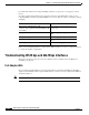
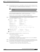
Displaying Interface Port Configuration
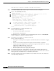
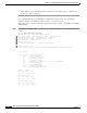
To display the interface configuration, use the following commands:
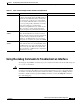
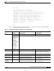
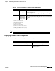
RX (Receive) Off
Flashing green
Red
LOS or interface module is shut down.
Cells are being received. LED blinks every 5 seconds and pulse rate
increases with data rate.
Alarm (LOF
1
, OCD
2
, AIS
3
, LOP
4
, RDI
5
, LCD
6
, UNEQ
7
, PLM
8
).
TX (Transmit) Off
Flashing green
Flashing yellow
Steady yellow
No transmit line activity indication.
Cells are being transmitted. LED pulse rate increases with data rate.
Loopback.
RDI.
1. LOF = loss of frame
2. OCD = out of cell delineation
3. AIS = alarm indication signal
4. LOP = loss of pointer
5. RDI = remote defect indicator
6. LCD = loss of cell delineation (OC-48c)
7. UNEQ = unequipped code (OC-48c)
8. PLM = payload label mismatch (OC-48c)
Table 5-5 OC-3c, OC-12c, and OC-48c Interface Module LED Descriptions
LED Status Description
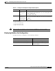
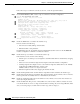
Command Purpose
show interfaces atm card/subcard/port Shows the status of the physical interface.
show atm interface atm card/subcard/port Shows the interface configuration.
show controllers atm card/subcard/port Shows the interface memory management
and error counters.