
Troubleshooting guide

5-26
ATM and Layer 3 Switch Router Troubleshooting Guide
OL-1969-02
Chapter 5 Troubleshooting Switch Router ATM Interface Connections
Troubleshooting OC-3c, OC-12c, and OC-48c Interfaces
Table 5-1 describes the Port status and Active defect errors the might appear, the cause of the error, and
a recommended solution.
If you determine that the physical interface is configured incorrectly, refer to the “Configuring
Interfaces” chapter in the ATM Switch Router Software Configuration Guide.
If the configuration of the interface is not the problem, use the information in OAM Loopback Testing,
page 5-9 to configure a hard loopback to test the interface.
Next, see the Using the debug Commands to Troubleshoot an Interface, page 5-19 to further troubleshoot
the interface.
If the interface is still not operating correctly, proceed with the troubleshooting process in Chapter 6,
“Troubleshooting Switch Router ATM Network Connections.”
Troubleshooting OC-3c, OC-12c, and OC-48c Interfaces
This section describes specific processes and commands used to troubleshoot the OC-3c, OC-12c, and
OC-48c interface modules.
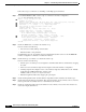
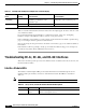
Interface Module LEDs
The interface module faceplate LEDs provide status information for individual single-mode and
multimode fiber-optic interface connections of the interface module. The LEDs are described in
Table 5-5.
Note Use the show controllers command to remotely display the LED status.
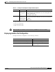
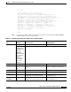
Sts-stream
scrambling
on It should match the Sts-stream
scrambling configuration of the
destination port.
Check the Sts-stream scrambling
configuration of the destination port.
Active Defects: None None None
See Table 5-1 for descriptions of the active defects that might appear.
Table 5-4 155-Mbps and 622-Mbps Port Adapter show controller Display
Field
Indication
(Severity) Error and Cause Recommendation
Table 5-5 OC-3c, OC-12c, and OC-48c Interface Module LED Descriptions
LED Status Description
LINK Off
Green
Carrier detect signal not received.
Carrier detect signal received.