
Troubleshooting guide

5-17
ATM and Layer 3 Switch Router Troubleshooting Guide
OL-1969-02
Chapter 5 Troubleshooting Switch Router ATM Interface Connections
Common show controller Troubleshooting Fields
Line Coding Errors
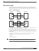
Each binary one or zero on a digital link represents an electrical pulse. Digital systems alternate the
polarity of each successive binary one to ensure a sufficient amount of voltage transitions. Such alternate
mark inversion (AMI) is designed to ensure that the receiving device properly synchronizes and
determines when the binary ones and zeros arrive. Two consecutive pulses with the same polarity (both
positive or both negative) create a bipolar violation.
In addition to AMI, DS-3 links also support bipolar three zero substitution (B3ZS) and high-density
bipolar three (HDB3), respectively. These line coding methods area also used to maintain
synchronization by ensuring a sufficient number of binary ones.
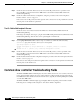
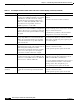
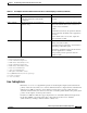
C2_MISMATCH
10
Typically encountered at initial turn-up or when
the far-end equipment is inadvertently
reconfigured.
Check the far end to ensure it is configured
correctly.
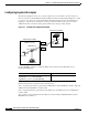
LOP
11
(Critical) Indicates that the far-end equipment is
malfunctioning.
1. Attach a multimode or single-mode fiber cable
between the transmit and receive connectors on
the OC-3c network interface
module.
2. If the alarm event clears, the problem is with the
far-end equipment. Troubleshoot the equipment as
necessary.
3. If the alarm event does not clear, replace the
network interface module.
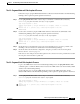
OOF
12
(Critical) 1. If a Cleared event is not received within 1
minute, reinsert the module.
2. Check the far-end equipment to ensure that it is
transmitting a valid OC-3 signal.
3. Check the optical fiber between the far-end and
near-end equipment for continuity.
4. If a problem persists, replace the network
interface module.
1. SLOS = Section Loss of Signal
2. SLOF = Section Loss of Frame
3. LAIS = Alarm Indicate Signal - Line
4. LRDI = Remote Defect Indication - Line
5. PAIS = Alarm Indicate Signal - Path
6. PRDI = Remote Defect Indication - Path
7. LCD = Loss of Cell Delineation
8. OCD = Out of Cell Delineation
9. FIFO_FULL = Framer FIFO Overflow
10. C2_MISMATCH = Received incorrect payload type
11. LOP = Loss of Pointer
12. OOF = Out of Frame
Table 5-1 Port Adapter and Active Defect Fields of the show controller Display (continued) (continued)
Indication (Severity) Error and Cause Recommendation