
Troubleshooting guide

5-16
ATM and Layer 3 Switch Router Troubleshooting Guide
OL-1969-02
Chapter 5 Troubleshooting Switch Router ATM Interface Connections
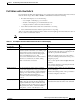
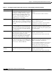
Common show controller Troubleshooting Fields
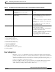
LRDI
4
(Major) RDI alarms are always reported upstream from the
detecting device. LRDI specifically comes back in
the K2 bits 6-8 and will override any existing
Automatic Protection Switching (APS) modes:
(APS 1+1) or APS status (BLSR). AIS-L is also
sent in bits 6-8 and is generally sent from a
SONET regenerator or other STE.
RDI - Line problems arise from the remote
interface.
Check the remote site for alarm conditions.
PAIS
5
(Minor) An upstream LTE that receives LAIS then sends
path AIS to the downstream PTE by setting H1 and
H2 bytes. The purpose is to alert the downstream
PTE of a defect on the upstream LET’s incoming
line signal.
This is sent by a site that has received LAIS. This
is a minor warning, and no action needs to be taken
except to monitor the far end.
If the alarms are persistent, verify the interface
configurations on both ends of the trunk.
PRDI
6
(Minor) Used only at the path level. A problem at the path
layer prompts PAIS to be sent downstream and
PRDI to be sent back upstream to let the traffic
provider know that there is a problem with their
circuit downstream.
A PRDI alarm usually indicates a problem two
sites away. If the alarm is persistent, check the
alarm status of neighboring sites, beginning with
the nearest neighbor.
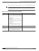
LCD
7
(Critical) Caused by short-term (milliseconds in duration)
incidents that clear as part of the normal course of
traffic management. Examples of traffic
management events include the freeing of buffer
space, recovery from parity errors at a higher
level, and recover after a brief loss of signal.
1. If a Cleared event status is not received within
1 minute, reinsert the module.
2. If the problem persists, replace the module.
OCD
8
(Critical) Number of times that a receiving device
recognizes the start and end of an ATM cell. The
header error control (HEC) field of the ATM cell
header is used to delineate ATM cells.
1. Check the far-end equipment to ensure that it is
functioning properly and configured for OC-3c
ATM mode with HEC cell delineation.
2. Loop the transmit signal back to the receiver at
the network interface module to verify that the
framing, section, line, and path are good.
3. If a problem persists, replace the module.
FIFO_FULL
9
(Critical)
Indicate a problem on the network interface
module that would interrupt downstream traffic
flow.
1. If a Cleared event status is not received within
1 minute, reinsert the module.
2. If the problem persists, replace the module.
Table 5-1 Port Adapter and Active Defect Fields of the show controller Display (continued) (continued)
Indication (Severity) Error and Cause Recommendation