
Troubleshooting guide

5-14
ATM and Layer 3 Switch Router Troubleshooting Guide
OL-1969-02
Chapter 5 Troubleshooting Switch Router ATM Interface Connections
Common show controller Troubleshooting Fields
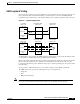
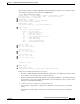
The following example of a show controllers command displays the typical location of the Port status,
Active Alarms, and Active Defects fields for a T1 interface:
Switch# show controllers atm 4/1/0
IF Name: ATM4/1/0, SUNI PDH Chip Base Address: A8F08000
IF Name: ATM4/1/0, framer Base Address: A8F09000
Port type: T1 Port rate: 1500 Kbps Port medium: UTP
Port status:Good Signal Loopback:None Flags:8008
showdow clk reg value AA
TX Led: Traffic Pattern RX Led: Traffic Pattern CD Led: Green
TX clock source: network-derived
T1 Framing Mode: ESF PLCP format
FERF on AIS is on
FERF on LCD is on (n/a in PLCP mode)
FERF on RED is on
FERF on OOF is on
FERF on LOS is on
LBO: between 0-110
Counters:
Key: txcell - # cells transmitted
rxcell - # cells received
lcv - # line code violations
ferr - # framing bit error event counter
bee - # bit error event, CRC-6 in ESF, Framing bit error in SF
b1 - # PLCP BIP errors
fe - # PLCP framing pattern octet errors
plcp_febe- # PLCP FEBE errors
hcs - # uncorrectable HEC errors
uicell - # unassigned/idle cells dropped
txcell:1596795, rxcell:1596814
lcv:2, ferr:0, bee:2
febe:0, b1:0, fe:0, plcp_febe:0, hcs:0, uicell:4294871705
PDH errored secs:
lcv:1, ferr:0, bee:1
febe:0, b1:0, fe:0, plcp_febe:0, hcs:0
PDH error-free secs:
lcv:1288627, ferr:1288628, bee:1288627
febe:0, b1:1288628, fe:1288628, plcp_febe:1288628, hcs:1288628
[Information Deleted]
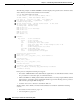
In the previous example the following errors appear:
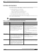
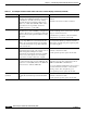
• Port status—LINE AIS LCD or line alarm indicate signal and loss of cell delineation. Table 5-1 lists
the port status errors and causes plus, recommended actions.
• TX Led and RX Led—Traffic pattern indicates this interface is receiving a signal, CD Led (Carrier
Detect) Green—detecting a carrier signal. Each interface type in the following sections provides a
table with the port adapter LED descriptions.
• Counters—these error counters are described in Table 5-2.
The Port status, Active Alarms, and Active Defects fields are described in detail in the following
sections:
• Port Status and Active Defects, page 5-15
• Line Coding Errors, page 5-17