
Troubleshooting guide

5-12
ATM and Layer 3 Switch Router Troubleshooting Guide
OL-1969-02
Chapter 5 Troubleshooting Switch Router ATM Interface Connections
Common show controller Troubleshooting Fields
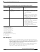
Step 2 Check the Success rate field. If the success rate is less that 100 percent, there is a problem on the
OC-3 155-Mbps connection between the ATM switch router and the Catalyst 5000 switch in the
manufacturing building.
Step 3 Check the cables and the interface configuration, using the procedures in the “Performing Basic
Interface Checks” section on page 5-1.
If the success rate is 100 percent, then this segment of the connection is not the problem. Proceed with
the next phase of the interface loopback test.
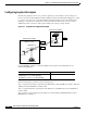
Test 3—End-to-End Loopback Process
Check the end-to-end connection between the DNS server and the Catalyst 5000 switch in the
manufacturing building.
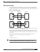
Following is an example of the steps to ping the entire ATM virtual path between the administration and
manufacturing buildings, with an end-to-end loopback signal in normal mode:
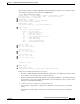
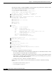
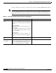
Step 1 Use the ping atm interface atm card/subcard/port command to confirm the VP connectivity.
AdminFl1Ls1# ping atm interface atm 4/0/0 2 end-loopback
Type escape sequence to abort.
Sending end-Loopback 5, 53-byte OAM Echoes to a neighbor, timeout is 5 seconds:
!!!!!
Success rate is 100 percent (5/5), round-trip min/avg/max = 1/2/4 ms
Step 2 Check the Success rate field. If the success rate is less that 100 percent, you have a problem on the
OC-3 155-Mbps connection between the ATM switch router and the Catalyst 5000 switch in the
manufacturing building.
Step 3 Check the cables and the interface configuration using the procedures in the “Performing Basic Interface
Checks” section on page 5-1.
If the success rate is 100 percent, then this segment of the connection is not the problem. Continue with
the next phase of the interface test.
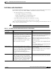
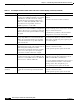
Common show controller Troubleshooting Fields
The show controllers atm command displays any active alarms and non-zero error counters, referred to
in the output as facility statistics. Non-zero values indicate a problem with the physical wire between
this ATM switch router interface and another network device, typically an Add-Drop Multiplexer (ADM)
or an another ATM switch.
The show controller command displays appear slightly different depending on the interface module.
Following are two examples with descriptions of the best troubleshooting fields: