
Troubleshooting guide


4-14
ATM and Layer 3 Switch Router Troubleshooting Guide
OL-1969-01
Chapter 4 Example Network
Example Networks
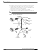
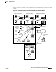
The typical core switch router configuration in Figure 4-11 shows the following connections:
• Gigabit Ethernet single-mode fiber core connection for redundancy to other buildings
• Gigabit Ethernet single-mode and multimode fiber distribution connection to ATM distribution
switch routers within the building
Figure 4-11 Typical Layer 3 and ATM Core Switch Router Configuration
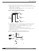
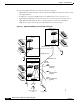
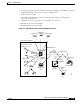
The typical distribution switch router configuration in Figure 4-12 shows the following connections:
• Gigabit Ethernet UTP distribution connection between core switch routers
• Gigabit Ethernet UTP distribution connection to the Cisco Systems Catalyst 5000 switches
• Gigabit Ethernet UTP access connection to individual servers
• 155-Mbps UTP or multimode fiber access connection through SVC with a CBR connection to
CODEC for videoconferencing
Figure 4-12 Typical Layer 3 and ATM Distribution Switch Router Configuration to Floor 1
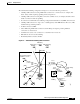
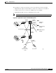
The administration building configuration in Figure 4-13 shows the following connections:
• Gigabit Ethernet UTP connections to e-mail servers
• Gigabit Ethernet UTP connections to DNS servers
Gigabit Ethernet
Marketing
building
Manufacturing
building
Administration
building
49996
Gigabit
Ethernet
Server farm
Videoconference
center
Gigabit Ethernet
CBR to
video
Gigabit
Ethernet
Gigabit
Ethernet
Gigabit Ethernet
49995