
Troubleshooting guide

4-12
ATM and Layer 3 Switch Router Troubleshooting Guide
OL-1969-01
Chapter 4 Example Network
Example Networks
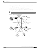
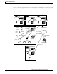
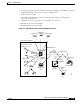
The engineering building in Figure 4-9 shows the following connections:
• Gigabit Ethernet single-mode fiber connections between the ATM core switch router on Floor 1 and
the campus backbone
• T1 CES access connection to CBR and QoS video CODEC for the video conference room
• Gigabit Ethernet UTP SVC connections from the access switch router to the enterprise servers
• Gigabit Ethernet UTP, multimode fiber, or single-mode fiber connection from distribution
ATM switch routers in each wiring closet to Fast Ethernet access switch routers
Figure 4-9 Engineering Building Layer 3 and ATM Connections
Administration
building
Manufacturing
building
Marketing
building
Videoconference
center
Server farm
T1 CES
49998
Wiring closet,
floor 1
Wiring closets,
floors 2 through 8
Wiring closet,
floor 9
Wiring closet,
floor 9
Gigabit Ethernet
Gigabit Ethernet
Gigabit Ethernet
Gigabit
Ethernet
CODEC