
Troubleshooting guide


4-10
ATM and Layer 3 Switch Router Troubleshooting Guide
OL-1969-01
Chapter 4 Example Network
Example Networks
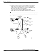
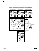
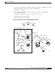
Example Mixed ATM and Layer 3 Network
This section uses the fictitious network described in the “Example ATM Network” section on page 4-2
to illustrate actual problems in troubleshooting a mixed ATM and Layer 3 switched network.
While the example network overview is the same as shown in Figure 4-1, there are additional redundant
Layer 3 Gigabit Ethernet connections between buildings, LAN switches, and some high-usage servers.
These redundant Gigabit Ethernet and Gigabit EtherChannel provide the high-capacity trunks needed to
connect these gigabit switches if the primary ATM connections should fail.
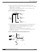
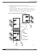
Physical Connections
The example network contains the following physical connections:
• Gigabit Ethernet—Connect distribution Layer 3 switch routers to Catalyst 5000 or Catalyst 6000
family switches
• T1 or E1—Using PVPs, connect to the WAN to reach remote sites such as WWW, FTP, Telnet, and
e-mail
• T3 or E3—Using PVPs, connect to the WAN to reach remote sites such as WWW, FTP, Telnet, and
e-mail
• T1 circuit emulation switch—Using PVPs, connect to private branch exchange (PBX) or, using
switched virtual circuit (SVC), connect to coder/decoder (CODEC) for constant bit rate (CBR)
video
• Frame Relay—Using PVC, connect to a telecommuter
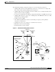
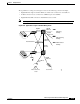
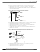
Virtual Connections
The example network in Figure 4-8 has the following virtual connections:
• PVP tunnels—Connect to the remote site through the public network to avoid signalling
• T1 CES access connection to CBR and QoS video CODEC for the video conference room