
Troubleshooting guide

4-7
ATM and Layer 3 Switch Router Troubleshooting Guide
OL-1969-01
Chapter 4 Example Network
Example Networks
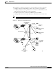
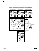
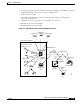
The typical Floor 1 wiring closet in Figure 4-4 shows the following connection examples:
• 622-Mbps single-mode fiber ATM core switch router connections to the backbone
• 25-Mbps port adapter providing 12 PVC access connections to CAD/CAM users with
SGI workstations whose NICs do not support signalling
• T1 CES connection access connections to CBR and QoS video CODEC
• 155-Mbps UTP connection through LANE SVC to Fast Ethernet access switch router
Note Each Fast Ethernet distribution switch connection has a redundant link. (See Figure 4-4.)
Figure 4-4 Typical Floor 1 ATM Wiring Closet
Videoconference
center
Server farm
12, 25-Mbps
CAD/CAM
users
Administration
building
Manufacturing
building
Marketing
building
622 SMF
622 SMF
622 SMF
LES LECS/BUS
to Catalyst
switches
155 UTP
Redundant links
T1 CBR to
video
ELAN to
servers
SVCs
10300