
Troubleshooting guide


4-3
ATM and Layer 3 Switch Router Troubleshooting Guide
OL-1969-01
Chapter 4 Example Network
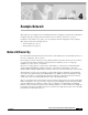
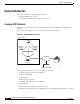
Example Networks
• Approximately 100 users per Catalyst 5000 or Catalyst 5500 switch. This example network requires
approximately 50 Catalyst 5000 or Catalyst 5500 switches:
–
One intermediate equipment closet per building that connects buildings with the ATM
distribution switch routers
–
Fiber-optic connections between wiring closets and intermediate equipment closets
–
One-half of the users are on VLAN 2; the other half are on VLAN 3
• Network 10.0.0.0 255.255.255.0
• 254 hosts per subnet
• Spanning tree and root bridges enabled
• No single point of failure
• Workgroup servers that are connected using either ATM or Fast Ethernet in Layer 2
• Enterprise servers (e-mail, Web, and meeting scheduling) located in the administration building with
the edge routers and firewall protection
• Switch routers that provide the following:
–
155-Mbps unshielded twisted-pair (UTP) Optical Carrier 3 (OC-3) connections to servers and
high-bandwidth users (computer-aided design [CAD], video, and voice) to the backbone
–
2,488-Mbps single-mode fiber (OC-48) connections to the core between buildings in the
intermediate wiring closets creating the backbone
–
T3 coaxial connections to the WAN
• Catalyst 5000 or Catalyst 600 family LAN switches provide the following:
–
Access and workgroup connection to individual users of the network
–
Workgroup server connections
–
Spanning-tree loop protection and network redundancy
• The remote site switch router has the following:
–
500 employees
–
750 total ports
• The telecommuter router has the following:
–
Dialup connections
–
ISDN
–
Frame Relay
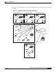
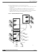
Physical Connections
The example network contains the following physical connections:
• 155-Mbps UTP—Using permanent virtual path (PVP) and LAN emulation (LANE), connect
distribution switch routers to Catalyst 5000 or Catalyst 6000 family LAN switches
• 622-Mbps multimode fiber and single-mode fiber—Using PVP, connect core switch routers with tag
switching enabled