
Troubleshooting guide


E-3
ATM and Layer 3 Switch Router Troubleshooting Guide
OL-1969-01
Appendix
Understanding show controllers Command Output
Connection Alarm Types
The following section provides troubleshooting steps to take if your ATM interface displays any of the
following alarms:
AIS (Alarm Indication Signal)
An AIS indicates an alarm raised on a line upstream from the ATM switch router.
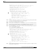
Follow these steps to correct an AIS alarm:
Step 1 Check the status of the adjacent network device to determine if the problem is there. If the problem is
not in the adjacent network device, go to Step 2.
Step 2 Ask your service provider to trace the source of the AIS signal.
LOF (Loss of Frame)
Cause of Alarm
A LOF condition typically happens in one of two situations:
• The configuration settings on the port are not correct for the line.
• The interface configuration is correct but the line is experiencing other errors that result in an LOF
alarm.
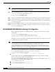
Follow these steps to correct an LOF alarm:
Step 1 Check to see if the framing format configured on the port matches the framing format on the line.
Step 2 Try the other framing format and see if the alarm clears.
Step 3 Work with your provider to configure a remote loopback on the affected interface, then run an unframed
bit error rate tester (BERT). This test will help determine if there are problems on the line.
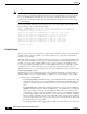
Parity Error (PE) Indicate the number of parity errors detected via the P-bit on DS-3 links and
via the BIP-8 field on E3 links (G.832). RFC1407 defines a P-bit parity error
event as the occurrence of a received P-bit code on the DS-3 M-frame that is
not identical to the corresponding locally-calculated code. Parity checks
detect changes to a frame during transmission. Digital links need to retain
the true value of a frame to ensure that the destination correctly interprets the
transmitted information.
Far-End Block Error
(FEBE)
The DS-3 M-frame uses P bits to check the line's parity. The M-subframe
uses C bits in a format called C-bit parity, which copies the result of the P
bits at the source and checks the result at the destination. An ATM interface
reports detected C-bit parity errors back to the source via a FEBE.
Rx Cell HCS Error
(HCSE)
ATM interfaces protect against changes to the cell header with a header error
checksum (HCS) field. The HCS detects errors only in the header and not in
the 48-byte payload. HCS errors indicate that source, destination or ATM
network corrupted the cell header in some way.
Table E-1 show controller Display Facilities Statistics and Explanations
Facility Statistic Explanation