
Troubleshooting guide


C-2
ATM and Layer 3 Switch Router Troubleshooting Guide
OL-1969-01
Appendix
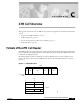
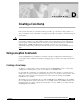
Formats of the ATM Cell Header
The UNI header consists of the following fields:
• GFC—4 bits of generic flow control that are used to provide local functions, such as identifying
multiple stations that share a single ATM interface. The GFC field is typically not used and is set to
a default value.
• VPI—8 bits of virtual path identifier that is used, in conjunction with the VCI, to identify the next
destination of a cell as it passes through a series of switch routers on its way to its destination.
• VCI—16 bits of virtual channel identifier that is used, in conjunction with the VPI, to identify
the next destination of a cell as it passes through a series of switch routers on its way to
its destination.
• PT—3 bits of payload type. The first bit indicates whether the cell contains user data or control data.
If the cell contains user data, the second bit indicates congestion, and the third bit indicates whether
the cell is the last in a series of cells that represent a single AAL5 frame.
• CLP—1 bit of congestion loss priority that indicates whether the cell should be discarded if it
encounters extreme congestion as it moves through the network.
• HEC—8 bits of header error control that are a checksum calculated only on the header itself.
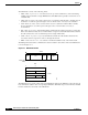
The NNI specification defines communications between switch routers. The format of the NNI header
is shown in Figure C-2.
Figure C-2 NNI Header Format
The GFC field is not present in the format of the NNI header. Instead, the VPI field occupies the first 12
bits, which allows switch routers to assign larger VPI values. With that exception, the format of the NNI
header is identical to the format of the UNI header.
VPI VCI PT HEC
C
L
P
Field length
in bits
12 16 3 1 8
40 bits
VPI VCI
VCI
VPI
VCI PT CLP
HEC
10410
840
1
2
3
4
5
Bits
Octets