
Troubleshooting guide

13-26
ATM and Layer 3 Switch Router Troubleshooting Guide
OL-1969-01
Chapter 13 Troubleshooting ATM Router Module Connections
Troubleshooting RFC 1577 on ATM Router Module Connections
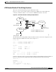
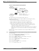
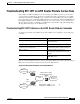
This example network is used in the following troubleshooting steps.
Follow these steps to troubleshoot the ATM router module, shown in Figure 13-10, configured with RFC
1577:
Step 1 Use the following commands to configure RFC 1577 for the example network shown in Figure 13-10.
Switch# config term
Switch(config)# interface atm 10/0/1.1 multipoint
Switch(config-if)# ip address 1.1.1.2 255.255.0.0
Switch(config-if)# atm arp-server nsap 47.009181000000009021418801.009021418801.00
Switch(config-if)# atm pvc 2 102 pd on inarp 5 interface ATM0/0/0 0 102
Switch(config-if)# exit
Switch(config)# interface atm 10/0/1.3 multipoint
Switch(config-if)# ip address 3.3.0.2 255.255.0.0
Switch(config-if)# atm arp-server nsap 47.009181000000009021418801.0050BD9B2160.0A
Switch(config-if)# atm pvc 2 103 pd on inarp 5 interface ATM0/0/1 0 103
Switch(config-if)# end
Switch#
Step 2 Use the show running-config command to confirm your configuration.
Switch# show running-config
Building configuration...
Current configuration:
!
!
interface ATM10/0/1.1 multipoint
ip address 172.20.52.41 255.255.255.224
atm arp-server nsap 47.00918100000000E04FACB401.00E04FACB401.00
atm pvc 2 102 pd on inarp 5 interface ATM0/0/0 0 102
!
The following process describes troubleshooting basic connectivity problems with RFC 1577 networks.
In the example shown in Figure 13-10, the Cisco 7500 router connected to Ethernet 1.1.0.0 is acting as
the ARP server.
Step 1 Using the show atm map command, confirm that both the switch router and the Cisco 7500 router
connected to Ethernet 3.3.0.0 have connections to the ARP server. If they are connected, they can ask
the ARP server for an IP-to-ATM address resolution.
Step 2 To test the switch router configuration, use the debug atm arp command on the switch router, to see
whether it is sending out an ARP request to the ARP server router.
Step 3 From the Cisco 7500 router connected to Ethernet 1.1.0.0 (and acting as the ARP server), confirm it is
receiving the ARP request and responding to it with a positive acknowledgment by using the debug atm
arp command.
Step 4 On the ARP server, use the debug atm arp command to confirm it is receiving the ARP requests and
responding with a positive acknowledgment.
When the IP-to-ATM address is resolved, the Cisco 7500 router connected to Ethernet 3.3.0.0 should be
able to make a call to the ATM address of the switch router ATM router module. If the Cisco 7500 router
still can not connect to the switch router ATM router module, the problem is probably the call setup.
Refer to the “Troubleshooting RFC 1483 on ATM Router Module Connections” section on page 13-20.