
Troubleshooting guide

13-24
ATM and Layer 3 Switch Router Troubleshooting Guide
OL-1969-01
Chapter 13 Troubleshooting ATM Router Module Connections
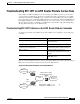
Troubleshooting RFC 1483 on ATM Router Module Connections
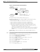
Step 11 Check the Rx cells fields. The numbers should have incremented from the previous display.
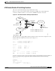
Step 12 From the downstream Cisco 7500 router use the ping command, with the IP address of the ATM router
module, to send five ICMP messages.
C7500# ping 2.2.0.2
Type escape sequence to abort.
Sending 5, 100-byte ICMP Echos to 2.2.0.2, timeout is 2 seconds:
.....
Success rate is 0 percent (0/3)
Step 13 Confirm that the Success rate is 0.
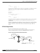
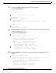
Step 14 From the downstream router, use the extended ping ip command, with the IP address of the ATM router
module, to send five 64-byte ICMP messages.
C7500#ping ip
Target IP address: 2.2.0.2
Repeat count [5]:
Datagram size [100]: 64
Timeout in seconds [2]:
Extended commands [n]:
Sweep range of sizes [n]:
Type escape sequence to abort.
Sending 5, 64-byte ICMP Echos to 2.2.0.2, timeout is 2 seconds:
.!.!.
Success rate is 40 percent (2/5), round-trip min/avg/max = 1/1/1 ms
C7500#
Step 15 Check the Success rate field. Note that the success rate improved to 40 percent after you changed the
ICMP datagram size to 64 bytes, from the default 100 bytes used in the previous ping command attempt.
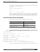
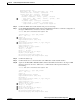
Step 16 Again use the show atm vc interfaces atm command with VPI 0 and VCI 109 on the ingress ATM
interface connected to the Cisco 7500 router.
Switch# show atm vc interface atm 0/0/0 0 109
Interface: ATM0/0/0, Type: quad_oc12suni
VPI = 0 VCI = 109
Status: UP
Threshold Group: 5, Cells queued: 0
Rx cells: 25, Tx cells: 4
Tx Clp0:4, Tx Clp1: 0
Rx Clp0:25, Rx Clp1: 0
Rx Upc Violations:9, Rx cell drops:14
Rx pkts:2, Rx pkt drops:8
Rx connection-traffic-table-index: 110
Step 17 Check the Rx cells field. Notice that the number is incrementing.
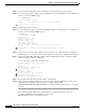
Step 18 Check the values in Rx Upc Violations, Rx cell drops, and Rx pkt drops fields. These values are also
incrementing proving that the aggressive policing, configured with the atm
connection-traffic-table-row index 110 ubr pcr 1 command setting the peak cell rate to 1, is working
correctly.
If you determine that the ATM router module interface is configured incorrectly, refer to the
“Configuring ATM Router Module Interfaces” chapter in the
ATM Switch Router Software Configuration Guide.