
Troubleshooting guide

13-18
ATM and Layer 3 Switch Router Troubleshooting Guide
OL-1969-01
Chapter 13 Troubleshooting ATM Router Module Connections
Troubleshooting LANE Clients on ATM Router Module Connections
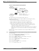
IF-MAP:
ATM10/0/1 Broute VC 92
Bcast VC 0
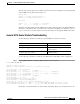
Using Broute VC 92, the Ethernet packet is switched across the backplane to the ATM router module at
ATM interface 1/0/1, where it propagates the CAM on the ATM interface with the following:
CAM Port atm 10/0/1
My-MAC=LEC101
My-Subnet=S2
Subnet S1
10.1.1.2=00ab.cdef.0001, S1.A, Fa 0/0/0
20.1.1.5=MAC_B, VPI0, VCI188
(Data Direct VC)
IF-MAP:
Fa 0/0/0 Broute VC 80
Bcast VC 0
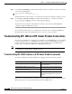
Using VPI 10 and VCI 188, the ATM router module transfers the Ethernet packets across the backplane
to ATM interface 9/0/3, for transmission out to the LANE cloud and subsequent delivery to the
destination Host.
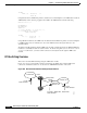
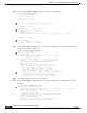
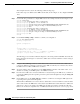
Troubleshooting IP switching with the ATM router module configured between the ATM and Ethernet
interfaces is essentially the same as described in the “Troubleshooting IP Layer 3 Connections” section
on page 11-25. However, you must confirm connections and adjacencies through the ATM router
module.
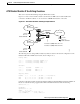
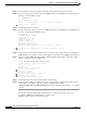
IPX Switching Overview
This section describes IPX switching using the ATM router module.
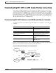
Figure 13-8 shows a network with a switch router that has an ATM router module installed and
connected to an Ethernet subnet on one side and two ATM ELAN networks on the other.
Figure 13-8 ATM Router Module IPX Switching Example Network
Host B
00ab.cdef.0002
Network 200
LEC2
ATM
BUS
Catalyst 8540
int a3/0/0.1 (ARM) LEC1, Network 200
00ab.cdef.0002
50256
Host A
00ab.cdef.0001
Ethernet
int fa1/0/0,
Network 100
Network 100