
Troubleshooting guide

13-17
ATM and Layer 3 Switch Router Troubleshooting Guide
OL-1969-01
Chapter 13 Troubleshooting ATM Router Module Connections
Troubleshooting LANE Clients on ATM Router Module Connections
ATM Router Module IP Switching Overview
This section describes IP switching using the ATM router module.
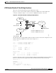
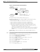
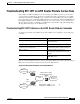
Figure 13-7 shows a network with a switch router that has an ATM router module installed and
connected to an Ethernet subnet on one side and two ATM ELAN networks on the other.
Figure 13-7 ATM Router Module IP Switching Example Network
The following are the routing, CEF, and adjacency tables created for the network configuration on the
Catalyst 8540 with an ATM router module, shown in Figure 13-7.
Routing Table:
10.1.0.0 is directly connected, FastEth 1/0/0
20.1.0.0 is directly connected, ATM3/0/0.1
30.1.0.0 is directly connected, ATM4/0/0.1
CEF Table
10.1.0.0 attached FastEth 0/0/0
20.1.0.0 attached ATM 3/0/0.1
30.1.0.0 attached ATM 4/0/0.1
Adjacency Table:
FastEth 0/0/0 10.1.1.2 00ab.cdef.0001 Interface No.
ATM 3/0/0.1 20.1.1.2 00ab.cdef.0002 Data VC
ATM 4/0/0.1 30.1.1.2 00ab.cdef.0003 Data VC
Using this configuration, traffic entering the Catalyst 8540 through the Fast Ethernet interface 0/0/0 from
Host A on network 10.1.0.0 propagates the CAM on the Ethernet interface with the following:
CAM Port FA 0/0/0
My-MAC=FE000
My-Subnet=10.1.0.0/16
Subnet 20.1.0.0/16
10.1.1.2=00ab.cdef.0001, S1.A, FA0/0/0
20.1.1.5=LEC101, S2.B, ATM10/0/1
ELAN1
20.1.0.0/16
ELAN2
30.1.0.0/16
LEC3
LEC4
ATM
ATM
BUS
Catalyst 8540
int a3/0/0.1 (ARM) LEC1, 20.1.1.5
int a4/0/1.1 (ARM) LEC2, 30.2.2.5
50255
Host B
10.1.1.2
00ab.cdef.0002
Host A
10.1.1.2
00ab.cdef.0001
Host C
30.1.1.2
00ab.cdef.0003
10.1.0.0/16
Ethernet