
Troubleshooting guide

13-13
ATM and Layer 3 Switch Router Troubleshooting Guide
OL-1969-01
Chapter 13 Troubleshooting ATM Router Module Connections
Troubleshooting LANE Clients on ATM Router Module Connections
Troubleshooting LECs Problems on the ATM Router Module Commands
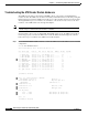
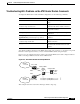
To display the ATM router module and LECs configuration, use the following commands:
To troubleshoot LECs configured on the ATM router module, refer to Chapter 7, “Troubleshooting LAN
Emulation Switching Environments,” and use normal LANE troubleshooting techniques.
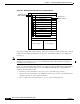
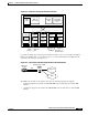
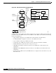
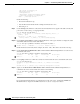
Figure 13-6 is an example network of a switch router with an ATM router module configured with two
LECs connecting an Ethernet network and an ATM network.
Figure 13-6 ATM Router Module LEC Example Network
This example network is used in the following troubleshooting steps.
Command Purpose
show lane client Displays the LEC configuration and
status
show atm vc interface
card/subcard/port.subinterface
Displays the ATM layer connection
information about the virtual connection.
show epc if-entry Displays interface entry information for
the specific interface.
show ip cef ip-address Displays Cisco Express Forwarding
information.
show epc ip-address interface {fastethernet |
gigabitethernet} slot/subslot/port ip-address
Displays the IP addresses of adjacent
interfaces.
show atm vc traffic interface atm
card/subcard/port VPI VCI
Displays information about the ATM
virtual connection.
ping ip-address Confirms the IP connection and
increments the transmit and receive cell
counters.
ELAN1
1.1.0.0/16
ELAN2
2.2.0.0/16
LEC3
LEC4
Cisco 7500
Cisco 7500
ATM
ATM
Catalyst 8540
+ARM
Catalyst 5500
LECS
LES
BUS
int a10/0/0.1 (ARM) LEC1, 1.1.1.2
int a10/0/1.1 (ARM) LEC2, 2.2.2.2
50253