
Troubleshooting guide

13-11
ATM and Layer 3 Switch Router Troubleshooting Guide
OL-1969-01
Chapter 13 Troubleshooting ATM Router Module Connections
Troubleshooting LANE Clients on ATM Router Module Connections
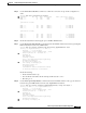
Step 2 Check the Ctrlr-Type field. Find the slot where the ATM router module (shown as “ARM PAM”) is
installed.
Step 3 Check the FPGA Version field. It should match the version listed in the
Hardware and Software Compatibility Matrix.
If it is not the correct version, update the FPGA image using the instructions in the “IOS Upgrade
Procedures” section on page 3-12.
Step 4 Check the CAM size and type.
Note The GBIC Vendor field indicates no vendor information. These Gigabit interfaces, included with the
ATM router module, are terminated on the board and only connect to the backplane.
If you determine that the interface is configured incorrectly, refer to the “Configuring ATM Router
Module Interfaces” chapter in the ATM Switch Router Software Configuration Guide.
Troubleshooting LANE Clients on ATM Router Module
Connections
The troubleshooting process for LECs configured on the ATM router module is very similar to the
troubleshooting process for ATM-to-ATM LANE connections described in Chapter 7, “Troubleshooting
LAN Emulation Switching Environments,” except for the following:
• All LANE VCs terminate on the ATM router module
• All ATM signaling is processed by the route processor and the ATM router module redirects LANE
control traffic to route processor
• All Service Specific Connection Oriented Protocol (SSCOP) packets are forwarded directly to route
processor
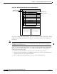
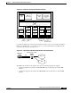
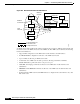
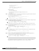
Figure 13-5 displays how the ATM router module installed in the Catalyst 8540 interacts with the other
elements of the ATM network and allows connections to Ethernet networks.