
Troubleshooting guide

13-9
ATM and Layer 3 Switch Router Troubleshooting Guide
OL-1969-01
Chapter 13 Troubleshooting ATM Router Module Connections
Hardware and Software Restrictions of the ATM Router Module
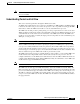
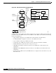
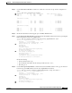
Figure 13-3 Packet Flow Through the ATM Router Module
Logically, the ATM router module appears and functions like a router connected with both Gigabit
Ethernet and ATM interfaces to the switch router on one side and the Ethernet and ATM networks
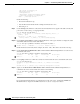
connected to the other side. See Figure 13-4.
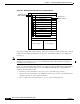
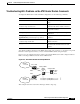
Figure 13-4 Logical View of the ATM Router Module in the Switch Router
The ATM router modules for the switch routers have the following aggregate throughput:
• 2.5 Gb/s throughput for the Catalyst 8540 MSR ATM router module with two internal ATM
interfaces
• 1.25 Gb/s throughput for the Catalyst 8510 MSR ATM router module with one internal ATM
interface
PNNI
table
ATM call
processing
Switch CPU
Routing
table
Forwarding
information
base
Line
module
ATM
ports phy
Switch fabric
Distributed
FIB
Line
module
OC12 ATM FastEther
Channel
50427
Line
module
Distributed
FIB
Distributed
FIB
ATM router
module
Line
module
Line
module
ATM
ports phy
OC48 ATM Gigabit
Ethernet
LANE
signalling
ATM cells
NNI
IPX packets or
Ethernet frames
GE
ATM
ATM router
module
Catalyst 8510 or 8540
52143
Ethernet
ATM
SI