
Troubleshooting guide

13-8
ATM and Layer 3 Switch Router Troubleshooting Guide
OL-1969-01
Chapter 13 Troubleshooting ATM Router Module Connections
Hardware and Software Restrictions of the ATM Router Module
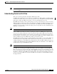
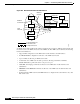
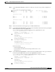
Figure 13-2 ATM Router Module Traffic Flow (Catalyst 8540 CSR)
The design of ATM router module software is intended to separate the control and data paths so that all
LANE control messages are handled by route processor, and all data is switched on the ATM router
module port.
Note The LightStream 1010 ATM switch allows configuration of LECs only on the controller port
subinterface (for example, the route processor atm2/0/0.subinterface). Thus, all VCs for signaling are
terminated on the route processor.
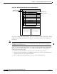
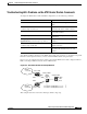
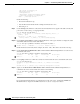
Figure 13-3 shows the functional architecture of a switch router with an ATM router module installed.
Traffic can enter the switch through any one of the ATM, Fast EtherChannel, or Gigabit Ethernet
interfaces. Then the traffic is either:
• switched across the switch fabric to the route processor for initial route processing
• switched across the switch fabric to the ATM router module to be returned to the switch fabric for
routing through any one of the remaining interfaces
• Layer 2 switched across the switch fabric to any one of the remaining interfaces
Interface slot
ATM interface module
FE or GE interface module
Interface slot
Route processor
Switch processor
Switch processor
Switch processor
Route processor
Interface slot
Interface slot
Interface slot
Interface slot
Power supply 1 Power supply 2
ATM router module
ATM cells NNI
LANE signalling
IPX packets/
Ethernet frames
31333