
Troubleshooting guide

11-36
ATM and Layer 3 Switch Router Troubleshooting Guide
OL-1969-01
Chapter 11 Troubleshooting Layer 3 Network Connections
Troubleshooting IP Layer 3 Connections
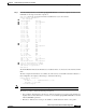
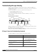
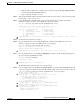
Figure 11-19 CAM Encoding Description
The Data fields in the display indicate the MAC address is written to the following:
• 0x009021DD—the first four bytes of the next-hop MAC address
• 0xDDDD0045—the last two bytes of the next-hop MAC address
• 0xDDDD0045—these last two bytes (in this example “0045”) indicate the following:
–
004 (12 bits)—the interface or Layer 3 VC number
–
5 (bit “0”)—Network-entry flag. A “1” indicates this is a host entry.
–
5 (bit “1”)—ATM VC number flag. A “0” indicates the 12-bit field is an interface number.
–
5 (bit “0”)—A “1” is a “My-IP flag” and indicates this is the IP address of this interface, and
that the packet should be forwarded to the route processor.
–
5 (bit “1”)—Entry valid flag. A “0” indicates this is an invalid entry.
Note The interface or VC number flag indicates the 12 bits are interpreted as either an interface or ATM
VC number. If this were an ATM router module, you could configure the VC to transmit on the ATM
side. The VC is then one of the following:
— a data direct VC for ATM LANE
— a PVC or SVC for 1483 or 1577, respectively
Step 8 If this process has not resolved the IP Layer 3 connection failure, repeat this same process for the reverse
path from the destination host, and verify that all other interfaces have similar CAM table entries.
Caution Be aware that asymmetrical routing could lead to multicast delivery on an alternate, unintended path,
if a forwarding algorithm based on Reverse Path Forwarding is used.
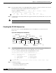
CAM encoding:
0x009021DDDDDD
004
6 Bytes
2 Bytes
DA MAC
Network-entry flag
IF or VC number flag
my-IP flag
Entry valid flag
12bits b b b b
010
5
1
I/F-no or
L3-VC
51539