
Troubleshooting guide

11-30
ATM and Layer 3 Switch Router Troubleshooting Guide
OL-1969-01
Chapter 11 Troubleshooting Layer 3 Network Connections
Troubleshooting IP Layer 3 Connections
Checking the IP CEF Adjacencies
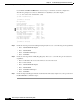
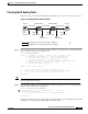
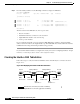
Follow these steps to verify the IP CEF adjacencies in the IP Layer 3 connection shown in Figure 11-17.
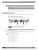
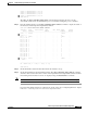
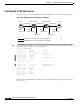
Figure 11-17 Displaying the IP CEF Adjacency Information
Step 1 Use the show ip cef command to verify that routes and attached devices appear in the table correctly
and point to the correct next hop or outgoing interface.
C8540CSR-1# show ip cef
Prefix Next Hop Interface
0.0.0.0/32 receive
10.19.134.36/32 10.19.134.36 Ethernet0
10.85.40.0/24 attached FastEthernet1/0/15
10.85.40.0/32 receive
10.85.40.254/32 receive
10.85.40.5/32 10.85.40.5 FastEthernet1/0/15
10.85.40.255/32 receive
.
(Information Deleted)
.
10.85.45.0/24 10.85.66.10 GigabitEthernet0/0/0
10.85.66.0/24 attached GigabitEthernet0/0/0
10.85.66.0/32 receive
10.85.66.10/32 receive
10.85.66.255/32 receive
224.0.0.0/4 drop
224.0.0.0/24 receive
255.255.255.255/32 receive
C8540CSR-1#
The information in the show ip cef command display is built from the IP routing table and resides on the
route processor.
Host A Catalyst 8540-2Catalyst 8540-1 Host B
10.85.40.0/24 10.85.66.0/24 10.85.45.0/24
.5 .254 .10 .5 .254 .5
MAC:
00:10.e3:aa...
Fast Ethernet connection (fast 1/0/15 on C8540-1)
Gigabit Ethernet connection (giga 0/0/0 on C8540-1)
MAC:
00:90.21:bb...
MAC:
00:90.21:dd...
MAC:
00:90.21:ff...
MAC:
00:90.21:cc...
MAC:
00:90.21:ee...
49994