
Troubleshooting guide

11-19
ATM and Layer 3 Switch Router Troubleshooting Guide
OL-1969-01
Chapter 11 Troubleshooting Layer 3 Network Connections
System Architecture
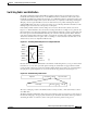
Note A shared CAM board and non-shared CAM board can co-exist in the same switch router.
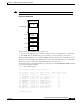
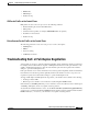
Figure 11-13 Shared CAM
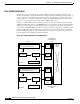
There are always five P2MP VCs in the switch router:
• One VC for all Gigabit processor interfaces, with two leaves for each Gigabit processor interface.
• Four P2MP VCs for each Ethernet processor interface, one corresponding to each channel.
With shared CAM, Gigabit processor interface P2MP remains the same. However, for Ethernet processor
interfaces with shared CAM, only channel-0 leaf is created. Other channel leaves are not created. This
allows a mix of private, shared, and dual CAM interfaces in the switch router.
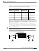
To determine what type of CAM is installed on your interface use the show hardware detail command
as shown in the following example:
Switch# show hardware detail
C8540 named Switch, Date: 10:41:12 UTC Thu Dec 7 2000
Slot Ctrlr-Type Part No. Rev Ser No Mfg Date RMA No. Hw Vrs Tst EEP
---- ------------ ---------- -- -------- --------- -------- ------- --- ---
0/* Super Cam 73-2739-03 D0 03170TAL May 03 99 0 3.1
0/0 8T1 IMA PAM 73-3367-02 B2 03100061 Mar 15 99 00-00-00 2.0 0 0
0/1 8E1 IMA PAM 73-3378-02 B2 03120056 Mar 25 99 00-00-00 2.0 0 2
2/* ARM PAM 73-4208-01 05 03150016 Apr 18 99 1.0
3/* ETHERNET PAM 73-3754-06 B0 03282WBF Jul 13 99 0 5.1
9/* OC48c PAM 73-3745-02 12 03190UXC Jun 28 99 2.1
10/* OCM Board 73-4165-01 04 03230ZZ2 Jun 28 99 10.1
10/0 QUAD 622 Gen 73-2851-05 A0 03160RVS Jun 16 99 5.0
11/* OC48c PAM 73-3745-02 12 03100015 Jun 28 99 2.1
12/* OCM Board 73-4165-01 04 03190UJV Jun 28 99 10.1
12/0 QUAD 622 Gen 73-2851-05 A0 03160S9J Jun 16 99 0 5.0
.
(Information Deleted)
14K/62K CAM
Entries per port
2K Interface
table
(S1, G1)
Port 0
Port 1
Port 2
Port 3
50430
2K Interface
table
2K Interface
table
2K Interface
table
Shared CAM