
Troubleshooting guide

11-17
ATM and Layer 3 Switch Router Troubleshooting Guide
OL-1969-01
Chapter 11 Troubleshooting Layer 3 Network Connections
System Architecture
CEFA
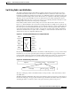
The CEFA is at the heart of the line card architecture. This ASIC has several key components that will
be discussed in detail. Each CEFA services four ports on the line card. In order to service eight ports,
two CEFAs are used per line card. On the Catalyst 8540, four CEFAs are used in order to service
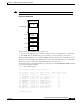
16 ports. Although not shown in Figure 11-11, the CEFA is responsible for all MAC layer functions. The
MAC is 10/100 autosensing and autonegotiating, if so configured. The MAC can also be run in either
full or half duplex mode.
Packets entering the switch port and having passed though MAC functions are stored in an internal block
of SRAM. This memory is 8 kilobytes in size, with 2K reserved for command instructions. This memory
is used to hold the packet while the appropriate lookups take place.
The CEFA microcontroller is a mini-route processor that is local to four ports on the Layer 3 enabled
ATM switch router line module. The microcontroller is designed to handle the traffic on each of the ports
in a fair manner. This means the CEFA must ensure that all packets have equal access into internal
memory and that lookups via the search engine are done fairly by arbitrating service between the four
ports. This is handled in a round-robin manner, meaning that the microcontroller cycles between each
port, processing requests as needed.
The microprocessor also has the critically important task of forwarding system messages such as
spanning tree BPDUs, routing advertisements, Cisco Discovery Protocol (CDP) packets, Address
Resolution Protocol (ARP) frames, and other control-type messages back to the route processor. Those
messages are forwarded by the CEFA to the route processor.
CEFA Search Engine
The search engine in the CEFA performs the address lookup or network output interface lookup. It
performs its lookup in the CAM table, which can hold either 16,000 or an optional 64,000 entries. The
search engine can make two types of switching decisions: Layer 2 based or Layer 3 based. With the
hardware-based access list feature card, the search engine can also perform lookups based on Layer 4
information. The search engine is therefore responsible for maintaining the Layer 2 MAC address table
and the Layer 3 FIB.
An incoming packet is placed into the internal memory. As soon as the first 64 bytes of the frame are
read into memory, the microcode signals the search engine with the relevant source or destination MAC
address, destination network, or Layer 4 port information. The search engine can then conduct a lookup
in the CAM table for the corresponding entry. Using a binary tree lookup method, the search engine can
hit a MAC address or perform a longest match on the destination network address very quickly. The
corresponding rewrite information, which is stored in the CAM table, is then delivered to the control
FIFO buffer of the Fabric Interface.
Fabric Interface
The final stage in packet switching within the Layer 3 enabled ATM switch router can now occur. The
switching CEFA now knows the port-of-exit for the packet based either on its MAC address or on the
Layer 3 IP or IPX network numbers. The packet must now be transferred across the switching fabric to
the destination. The Fabric Interface is responsible for preparing the packet for its journey across the
switching fabric.
The Fabric Interface consists of two main components: the frame FIFO buffer and the control FIFO
buffer. Figure 11-11 shows the internal memory of the CEFA, its direct connection into the frame FIFO
buffer, and the direct connection from the search engine into the control FIFO buffer. When the search