
Troubleshooting guide

11-16
ATM and Layer 3 Switch Router Troubleshooting Guide
OL-1969-01
Chapter 11 Troubleshooting Layer 3 Network Connections
System Architecture
Line Card Architecture
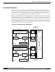
The last major component of the Layer 3 enabled ATM switch router architecture is the line cards.
Because the switch uses a distributed architecture, the line cards must be intelligent enough to make both
Layer 3 and Layer 2 forwarding decisions at wire speed for all media types, as well as enforce QoS
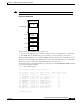
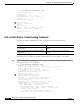
policies. Figure 11-11 details the architecture of the Layer 3 enabled ATM switch router line cards. In
Figure 11-11, notice that the Catalyst 8540 uses four CEFAs per line card.
The Layer 3 enabled ATM switch router line cards are based on the Cisco Express Forwarding ASIC
(CEFA). The CEF ASIC is based on the MMC Ethernet processor interface ASIC. It is called the CEF
ASIC since the Cisco Express Forwarding mechanism is programmed into the ASICs. This ASIC is
responsible for the Ethernet MAC layer functions, address or network lookup in the content-addressable
memory (CAM) table, and forwarding of the packet with its correct rewrite information to the Fabric
Interface. The Fabric Interface is also resident on the line card and is responsible for the packet rewrite,
QoS classification, and signaling to the Frame Scheduler.
Figure 11-11 Catalyst 8540 CSR Line Card Architecture
8K Internal Memory (Includes 2K
for command instructions)
16K or 64K CAM
Micro-
controller
Search
engine
Frame
FF0
Control
FF0
CEF ASIC
Ports 0-3
8K Internal Memory (Includes 2K
for command instructions)
16K or 64K CAM
Micro-
controller
Search
engine
CEF ASIC
Ports 4-7
Fabric
Interface
Frame
FF0
Control
FF0
Fabric
Interface
Shared
memory
fabric
1.25Gbps into
Shared memory
Fabric
1.25Gbps into
Shared memory
Fabric
49992