
Troubleshooting guide

11-15
ATM and Layer 3 Switch Router Troubleshooting Guide
OL-1969-01
Chapter 11 Troubleshooting Layer 3 Network Connections
System Architecture
how packets are switched out of the fabric, because there is plenty of bandwidth available. However, if
a link is congested, WRR services each queue per port based on the priority set by the network manager.
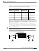
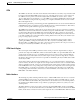
For example, look at the weights assigned by a network manager in Table 11-1.
Based on the priorities and weights provided, the Frame Scheduler services QoS-0 more often, granting
queue 53 Mbps out of the 100 Mbps possible on the output link. The second queue, QoS-1, receives 27
Mbps of the bandwidth, and so forth. These commands are set globally on the switch router and function
the same for all ports on the switch.
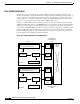
The switch router also allows you to override the global QoS settings by allowing port-to-port
communications to have a different level of priority. You have the option of configuring bandwidth based
on a source-destination, destination, or source basis and provide weights based on certain IP addresses
having more bandwidth then others.
Note This feature is available with the hardware access list daughter card installed on an Ethernet interface
module installed in the Catalyst 8510 CSR.
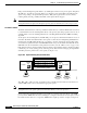
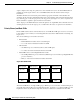
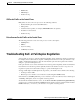
Figure 11-10 WRR Scheduling and Bandwidth Allocation
Table 11-1 Sample WRR Priority Weights
Quality of Service
Priority
Weight Given by
Network Manager
Bandwidth Assignment
Calculation
Bandwidth Assigned
QoS-0 8
=(8/(8+4+2+1)) x 100
53 Mbps
QoS-1 4
=(4/(8+4+2+1)) x 100
27 Mbps
QoS-2 2
=(2/(8+4+2+1)) x 100
13 Mbps
QoS-3 1
=(1/(8+4+2+1)) x 100
7 Mbps
Queue 0 - HH-P- 53 Mbps
Queue 1 - HL-P - 27 Mbps
Queue 2 - LH-P - 13 Mbps
Queue 3 - LL-P - 7 Mbps
Shared Memory Fabric
SI SI
Line Card Line Card
High Priority
User A
High Priority
User B
Interface Fast Ethernet 0/2
49991