
Troubleshooting guide

11-14
ATM and Layer 3 Switch Router Troubleshooting Guide
OL-1969-01
Chapter 11 Troubleshooting Layer 3 Network Connections
System Architecture
Each port transmitting through the fabric is, by default, placed in the lowest-priority queue. This places
all traffic at a “best-effort” QoS level. When you configure a policy, that traffic is transmitted in the
queue corresponding to the specified IP precedence. That queue is granted more service, thereby
reducing latency and the possibility that traffic on that queue will be dropped.
Note All management and control plane traffic, such as BDPU information, routing protocol updates, and
management frames are placed in the highest-priority queue for transmission to the route processor.
The Frame Scheduler
The Frame Scheduler has two main responsibilities within the Layer 3 enabled ATM switch router: first,
to schedule frames into the switching fabric based on the priority queue being requested, and second, to
schedule frames out of the switching fabric based on the Weighted Round Robin (WRR) scheduling
algorithm.
At the input to the switching fabric, the CEF ASIC posts a request to the Frame Scheduler for access to
the fabric. The Frame Scheduler handles each request in a time-division multiplexing (TDM) fashion,
meaning that each CEF ASIC will have the opportunity to clock an entire frame into the fabric when
access has been granted. Because each CEF ASIC handles four ports, the Frame Scheduler allows the
CEF ASIC to clock in a maximum of four packets into memory (see the “CEFA” section on page 11-17).
Each packet in memory has an internal routing tag added to the beginning which, as mentioned earlier,
contains the port of exit, queuing priority, and drop priority. Based on the routing tag, the input Frame
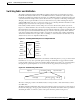
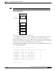
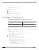
Scheduler places the packet in the correct queue (see Figure 11-9).
Figure 11-9 Input Scheduling and Queue Allocation
The “HH,” “HL,” “LH,” and “LL” designations refer to the IP precedence fields used by the Layer 3
enabled ATM switch router to determine the appropriate queue.
Note Although not shown, a fifth, critical high-priority routing tag is added to the beginning of all
management and control plane packets for immediate delivery to the route processor.
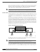
On the output side, the Frame Scheduler is responsible for servicing each queue based on the WRR
priority scheme. WRR allows the network manager to configure how much service each queue receives.
In a situation where there is no congestion, WRR and the weights provided do not play a real part on
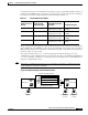
Fast Ethernet 0/2. Queue 0 - HH-P
Fast Ethernet 0/2. Queue 1 - HL-P
Fast Ethernet 0/2. Queue 2 - LH-P
Fast Ethernet 0/2. Queue 3 - LL-P
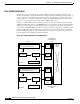
Shared Memory Fabric
SI SI
Line Card Line Card
High Priority
User A
High Priority
User B
Fast Ethernet 0/2
49990