
Troubleshooting guide

11-13
ATM and Layer 3 Switch Router Troubleshooting Guide
OL-1969-01
Chapter 11 Troubleshooting Layer 3 Network Connections
System Architecture
Switching Fabric and Arbitration
The Catalyst 8540 and Catalyst 8510 CSRs have different shared-memory architecture and system
bandwidth. The Catalyst 8540 is based on a 12-MB shared-memory architecture with a total system
bandwidth of 40 Gbps. The Catalyst 8510 is based on a 3-MB shared-memory architecture with a total
system bandwidth of 10 Gbps. Both systems shared memory is completely nonblocking, meaning that
all input ports have equal and full access into the shared memory for packet switching. The Layer 3
enabled ATM switch router also provides four queues per port, allowing the Frame Scheduler to make
intelligent QoS decisions based on the priority of each queue.
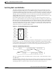
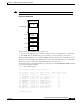
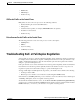
In the Catalyst 8540, each line card has 5-Gbps access into the shared memory fabric as shown in
Figure 11-7. This bandwidth is also divided into 2.5 Gbps transmit and 2.5 Gbps receive paths into the
fabric. This allows for nonblocking switching capacity within the switching system by ensuring that each
line card is given more bandwidth than all of the ports on the line card can generate. Each of the line
cards in the Catalyst 8510 is allotted 2.5 Gbps of capacity into the fabric. The 2.5-Gbps bandwidth is
divided into transmit and receive paths, each of 1.25 Gbps, to ensure that both reads and writes to the
shared memory can be accomplished simultaneously.
Figure 11-7 Switching Bandwidth per Slot on Catalyst 8540 CSR
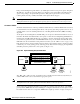
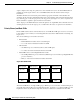
Because the Layer 3 enabled ATM switch router includes nonblocking memory, every port in the switch
has full access to every other port. Each packet entering the switch fabric is tagged with an internal
routing tag. This routing tag provides the switching fabric with the appropriate port of exit information,
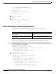
the QoS priority queue the packet is to be stored in, and the drop priority, shown in Figure 11-8.
Figure 11-8 Internal Routing Label Format
The 4 byte routing tag contains a 20-bit label value, a 3-bit QoS value, a 1-bit stack indicator, and an
8-bit TTL value.
The Fabric-Switching ASIC (FSA) then queues each packet into memory and creates a pointer, based on
the internal routing tag, to the appropriate destination port. The Frame Scheduler is then responsible for
scheduling the frame out of memory based on the queue where the packet is being stored.
Shared
memory
fabric
5Gbps
at slot 0
5Gbps
at slot 1
5Gbps
at slot 2
5Gbps
at slot 3
5Gbps
at slot 9
5Gbps
at slot 10
5Gbps
at slot 11
5Gbps
at slot 12
49988
Payload IP header Label Layer 2 header
Label (20) QoS (3) S (1) TTL (8)
49989