
Troubleshooting guide

11-12
ATM and Layer 3 Switch Router Troubleshooting Guide
OL-1969-01
Chapter 11 Troubleshooting Layer 3 Network Connections
System Architecture
CEF avoids the potential overhead of continuous cache churn by using a FIB on the line card for the
destination switching decision. The FIB mirrors the entire contents of the IP and IPX routing table. This
means that there is a one-to-one correspondence between FIB table entries and routing table prefixes;
therefore, a route cache does not need to be maintained.
Note Although CEF has been specified for IP, it also applies to IPX as well.
CEF Operation
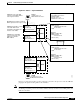
CEF provides features comparable to fast switching, including load sharing, recursive route resolution,
and access lists. CEF uses two tables maintained in the SRP and downloaded to the line cards: the FIB
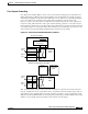
and adjacency table. The FIB table is used for making forwarding decisions. The adjacency table
maintains the adjacent nodes, and the link-layer information (such as packet rewrite information)
necessary to reach that adjacent node. Every entry in the FIB table has a pointer to a corresponding entry
in the adjacency table shown in Figure 11-6.
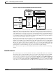
Figure 11-6 FIB and Adjacency Table
The FIB table is populated by callbacks (inputs) from the routing table. After a route is resolved, it points
to a next hop, which should be an adjacency. This step is done at the SRP and then downloaded to the
line cards, allowing the line cards to maintain a current topology of the network, which enables rapid
switching decisions (within 10 ms) as well as fast convergence in the event of a routing topology change.
The FIB is modified when a route is added, removed, or changed in the routing table. This information
is immediately downloaded to the line cards.
The adjacency table is also populated by callbacks from the routing protocols, which include information
such as next-hop information and (source, group [S,G]) interfaces for multicast groups. Adjacencies are
added when a protocol detects that there is an adjacent node via the routing protocol. When a packet
arrives at the ingress port, the CEF ASIC performs a FIB lookup based on the destination IP address.
The matching FIB entry points to an adjacency entry, which in turn provides the valid link layer rewrite
and outgoing interface. The packet is forwarded based on this information. Figure 11-6 shows the
relation of the FIB to the adjacency table.
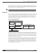
System Buffers
FIB Table
Dest IP
1.1.1.2
1.1.2.3
10.7.2.3
aaaa.bbbb.cccc
aaa1.bbb2.ccc3
bbb2.ccc2.ddd3
Gigabit 1/0/0
Gigabit 1/1/0
Gigabit 1/1/1
Next-Hop
Direct
1.1.2.0
2.2.2.4
Packet Memory Adjacency Table
List of Next-hop Devices
MAC Addresses Output Interface
Switching Fabric
49987