
Troubleshooting guide

11-10
ATM and Layer 3 Switch Router Troubleshooting Guide
OL-1969-01
Chapter 11 Troubleshooting Layer 3 Network Connections
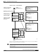
System Architecture
Routing Protocols
The route processor is responsible for running all of the routing protocols shown in Table 11-1 on the
Layer 3 enabled ATM switch router. Other protocols, such as AppleTalk, DECNet, and VINES are
bridged in the switch.
s
Note The Catalyst 8540 CSR is designed to support multiprotocol routing.
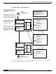
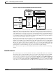
Most importantly, the route processor is responsible for maintaining the routing table. By using Cisco
Express Forwarding, the route processor creates a FIB, which contains a subset of the routing table. The
FIB is based on a topology map of the network, allowing routing to take place via the network topology
at high speed. The FIB is then downloaded to the line cards, allowing the line cards to make Layer 3
routing decisions without having to interrupt the route processor. This capability allows the Layer 3
enabled ATM switch router to forward all frames at wire speed for all ports. The FIB and Cisco Express
Forwarding are also described in the “Line Card Architecture” section on page 11-16.
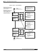
The route processor is also responsible for maintaining state information regarding multicast routing.
The Layer 3 enabled ATM switch router supports PIM (sparse mode and dense mode) as well as Distance
Vector Multicast Routing Protocol (DVMRP) interoperability. The route processor is responsible for
responding to and forwarding joins and leaves as well as responding to pruning messages sent by PIM.
Multicast forwarding takes place at the line card level.
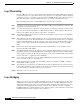
Layer 2 VLAN and Switching
Although the switching decisions are made at the line cards, the route processor is still responsible for
maintaining Layer 2 information. The route processor is responsible for bridge group configuration and
spanning tree calculation.
Bridge groups are configured on the Layer 3 enabled ATM switch router in the same way they are in
other Cisco routers. Instead of routing traffic to an outgoing interface, the traffic is bridged via its Layer
2 address. Integrated Routing and Bridging (IRB) is also supported in the Layer 3 enabled ATM switch
router in order to support both bridging and routing at the same time.
Spanning tree information within the switch is maintained by the route processor. This includes
calculation of the root bridge, optimum path determination to the root, and determining the forwarding
and blocking links.
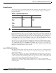
Table 11-1 Supported Routing Protocols
IP Networks IPX Networks AppleTalk Networks
RIP
RIP-2
OSPF
IGRP
EIGRP
BGP
IPX RIP
EIGRP
RTMP
EIGRP
AURP